
Third batch start and stop cycle control circuits
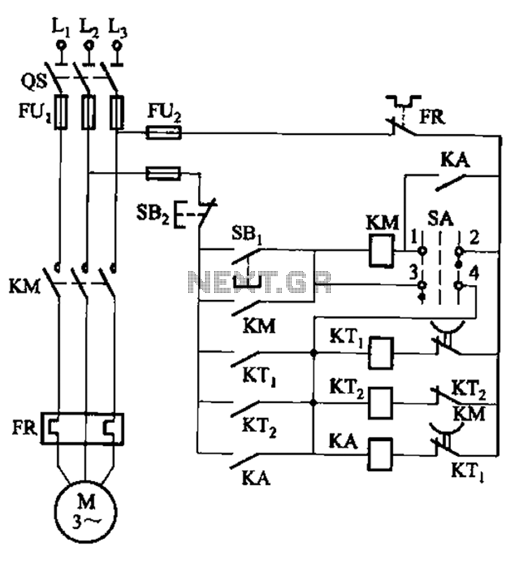
The circuit employs two relays, which play a critical role in automating the motor control process. The first relay is responsible for initiating the motor operation, while the second relay manages the motor's intermittent running cycle. This dual-relay system enhances the circuit's functionality, allowing for various operational modes.
When the switch SA is placed in the right position, the circuit transitions to a continuous run mode. In this configuration, the motor receives a constant supply of power, enabling it to operate without interruption. The design of the circuit ensures that the relays can handle the necessary current and voltage levels while providing reliable operation over extended periods.
The use of relays adds a layer of safety and control, as they can isolate the motor circuit from the power supply when not in use, reducing the risk of electrical hazards. The automatic cycle run feature allows for efficient operation in applications where intermittent motor activity is required, such as in conveyor systems or automated machinery.
Overall, the circuit design is versatile, catering to both intermittent and continuous operation modes, making it suitable for various industrial applications. The careful selection of components and their arrangement ensures optimal performance and reliability in automatic control scenarios. Circuit shown in Figure 3-78. The time line also use two relays to achieve automatic control, but the line structure than simple. The line can be achieved intermittently motor automatic cycle run, it can run continuously (switch SA placed the figure to the right position).
Related Circuits
Nikon infrared remote control with special features for interval shots, multiple shots, and continuous shots. The Nikon infrared remote control is designed to enhance the photography experience by allowing users to capture images without physically touching the camera. This remote...
The circuit operates based on the interaction between an infrared light-emitting diode (VD1) and an infrared receiver diode (VD2). When VD1 emits infrared radiation, it is detected by VD2, which causes a decrease in its internal resistance. This change...
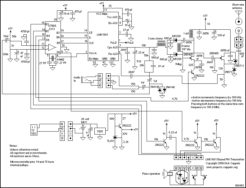
An LMX1601 Phase locked loop, a discreet FET VCO, and an AVR microcontroller combine to make a stable, easy to use monophonic FM transmitter that includes an audio activated switch that turns the transmitter on only when it is...
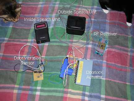
Our present car controller runs on a single PIC16F870 micro and provides functions for remote door locks, headlight reminder, and car finder. It is constructed using wire-wrap to allow for future expansion and is mounted using Velcro on the...
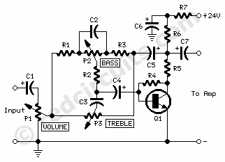
P1 47K logarithmic potentiometer; P2, P3 47K linear potentiometers; R1, R3, R5 4.7K 1/4W resistors; R2 22K 1/4W resistor; R4 1M 1/4W resistor; R6 1.8K 1/4W resistor; R7 560Ω 1/4W resistor; C1, C4, C5, C7 10 µF 63V electrolytic...
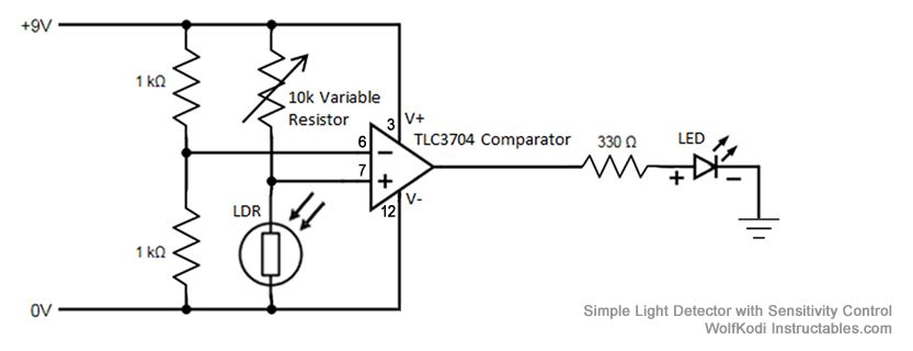
The schematic diagram for the circuit is provided in the accompanying image. As indicated by its name, a comparator is designed to compare two specified voltages. The circuit includes a pair of 1K resistors. A comparator circuit typically utilizes operational...
Warning: include(partials/cookie-banner.php): Failed to open stream: Permission denied in /var/www/html/nextgr/view-circuit.php on line 713
Warning: include(): Failed opening 'partials/cookie-banner.php' for inclusion (include_path='.:/usr/share/php') in /var/www/html/nextgr/view-circuit.php on line 713