
One fan Natural wind simulator circuit
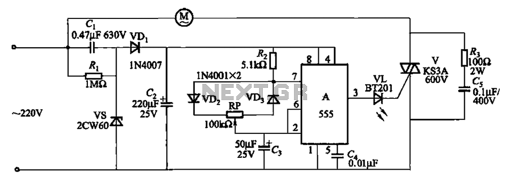
The circuit operates by employing the 555 timer IC in astable mode, which generates a square wave output that controls the fan's operation. When powered, the circuit initiates a cycle where the fan operates at a specified speed. As the cycle progresses, the output from the 555 timer gradually decreases, leading to a reduction in the fan's speed. This gradual decrease in airflow allows for a smoother transition to a complete stop, enhancing user comfort and reducing mechanical stress on the fan.
The potentiometer RP serves as a critical component for tuning the circuit's timing characteristics. By adjusting RP, the user can modify the resistance in the timing network, thereby altering the frequency of the oscillation and the duration of the fan's operation before it begins to slow down. This flexibility allows the circuit to be customized for various applications, depending on the desired airflow characteristics and stopping behavior.
The overall design of the circuit emphasizes efficiency and user control, making it suitable for applications where gradual airflow reduction is preferred, such as in HVAC systems or electronic cooling systems. The use of the 555 timer IC ensures reliability and ease of implementation, as it is a widely available and versatile component in electronic design. Circuit shown in Figure 3-8. It allows the fan when the turn stop, stop for a gradually increasing air volume decreases by a stop, so the cycle repeated. It uses 555 IC A compo sed of self-excited multivibrator control. Adjustment potentiometer RP, the circuit can change the cycle time.
Related Circuits
U1 is a 3817 integrated circuit produced by Fairchild Corporation. It is capable of directly driving a display and can operate in both 12-hour and 24-hour formats. Additionally, it can generate a clock sound and activate radios at scheduled...
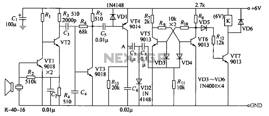
The circuit consists of transistors VT1 through VT7 and other components. Due to the weak signal received from the transmitter, the circuit employs a multi-stage amplifier to enhance the output. This output generates a square wave pulse signal to...
This circuit is a simple analog multiplier. The operation of the circuit can be understood by considering A2 as a controlled gain amplifier that amplifies V2, with its gain dependent on the ratio of the resistance of PC2 to...

This circuit is a compact timer designed to keep the headlights of a car illuminated for approximately 1.5 minutes before automatically turning them off. By integrating this circuit into a vehicle, users can access dark areas without the need...
Another unit of graphic equalizer with five bands. The primary distinction from other circuits is the use of transistors instead of integrated circuits (ICs), and the power supply operates at +/- 24V DC, which ensures low distortion and greater...
A circuit is required where, upon power application, a timer triggers, keeping a relay in the off state. Once the timer completes its cycle, the relay will activate. The circuit design consists of a timer integrated with a relay to...
Warning: include(partials/cookie-banner.php): Failed to open stream: Permission denied in /var/www/html/nextgr/view-circuit.php on line 713
Warning: include(): Failed opening 'partials/cookie-banner.php' for inclusion (include_path='.:/usr/share/php') in /var/www/html/nextgr/view-circuit.php on line 713