
Intermittent start-stop cycle control circuit of seven b
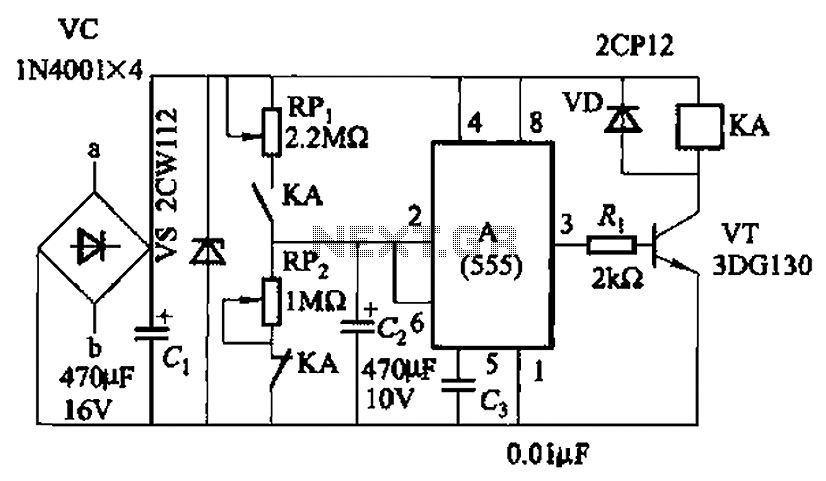
The circuit utilizes the 555 timer IC in an astable configuration to create a pulse-width modulation (PWM) signal that drives the motor. The frequency and duty cycle of the PWM signal are determined by the resistors RPi and RPz, along with a timing capacitor connected to the 555 IC. By adjusting these potentiometers, the user can fine-tune the duration that the motor remains in operation versus the duration it remains off, allowing for flexible control over the motor's performance.
In this configuration, the 555 timer operates by charging and discharging the timing capacitor, which generates a square wave output. This output can be connected to a transistor or a relay, which acts as a switch to control the power supplied to the motor. When the output from the 555 IC is high, the transistor is turned on, allowing current to flow through the motor and initiating its operation. Conversely, when the output is low, the transistor turns off, cutting power to the motor and halting its operation.
The choice of components, such as the specific values of RPi and RPz, will affect the motor's operational characteristics, including its speed and the responsiveness of the start/stop cycles. Proper selection of the timing capacitor is also crucial, as it influences the frequency of the PWM signal. This circuit design is particularly useful in applications requiring automated control of motor functions, such as in robotic systems, automated doors, or conveyor belts. Circuit shown in Figure 3-82. It uses 555 IC A motor to achieve automatic control of start and stop cycles. Adjust potentiometer RPi and RPz, respectively, to change the motor running and stop times.
Related Circuits
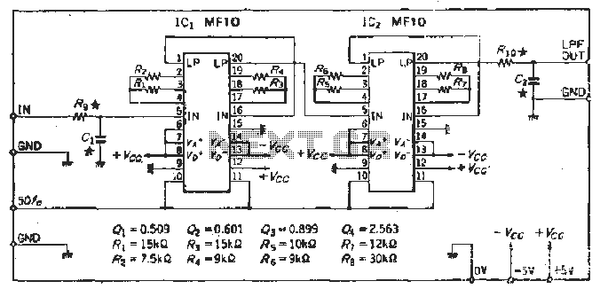
To create a Butterworth low-pass filter with a 12 dB/octave roll-off, four second-order (12 dB/oct) filter blocks are connected in series. This configuration is intended to achieve flat response characteristics across the frequency spectrum. The values for each stage...
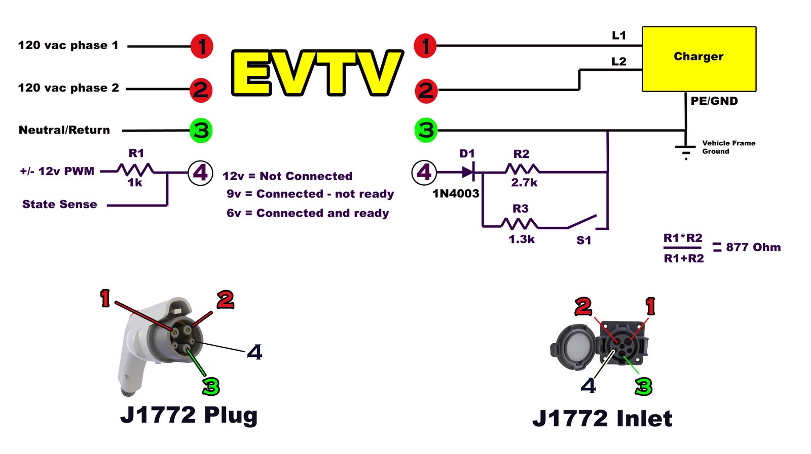
Building battery boxes for the Speedster. Although this topic may not seem thrilling, builders converting vehicles to electric drive often discover that the process of making a car run on battery power is relatively straightforward. However, about 50% of...
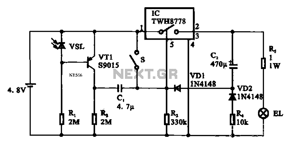
Automatic emergency lamp circuit featuring an electronic switch integrated circuit. This circuit is designed for automatic emergency lighting. The system operates based on ambient light conditions; when light levels are low at night, the circuit activates the emergency lamp....
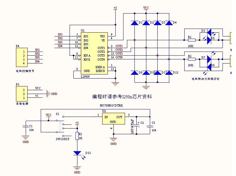
The L298N driver module incorporates the ST L298N chip, commonly utilized to drive two DC motors with voltage ratings between 3V and 30V. It features a 5V output interface that provides power for 5V single-chip circuitry and supports 3.3V...
The receiver circuit depicted in the figure requires the insertion of a plug into the radio headphone jack. When the radio receiver detects a signal from the transmitter, an audio signal is output from the jack. This signal is...
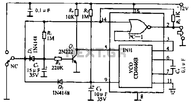
The figure illustrates a circuit involving dark tomb electric locks, specifically the fti: al: 4046B and XOR gate as the primary control mechanism. It emits pulses and utilizes silicon for successive pulse generation. The circuit operates with a normal...