
2Y- connection two-speed motor contactor control one circuit
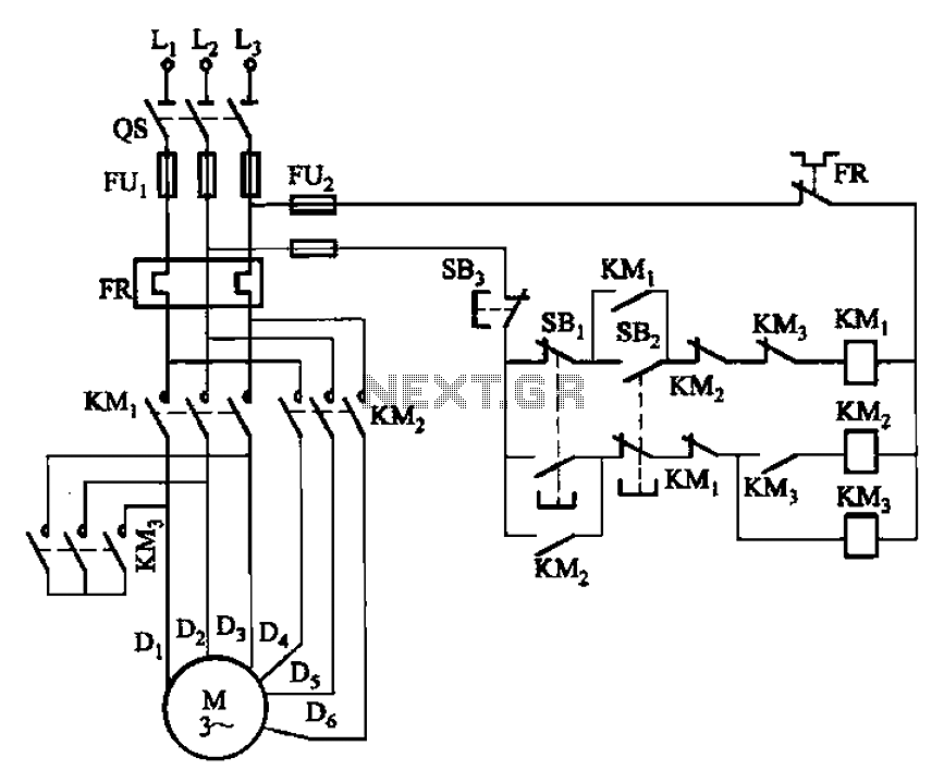
The circuit operates by utilizing a motor control setup that integrates multiple buttons to manage the speed and operation of the motor. The low-speed button (SBz) serves to initiate the motor at a reduced speed, ensuring a gradual start-up and minimizing mechanical stress. When SBz is pressed, it completes a circuit that energizes the relay KMa, which subsequently engages the first contact of the stator winding. This initial activation is crucial for establishing the motor's operational state.
Once KMa is engaged, the next relay, KMz, is activated, allowing the motor to draw power efficiently. The sequential activation of these relays is essential for controlling the motor's speed and preventing sudden surges in current. The design incorporates a safety feature to mitigate the risk of damage to the main contact KM3, which could occur if the motor were to receive excessive current during start-up. By ensuring that the relays engage in a controlled manner, the circuit protects the components from potential burnout.
In addition to the operational buttons, the circuit includes a stop button (SB3), which provides a means to halt the motor's operation safely. This button interrupts the power supply to the motor, allowing for immediate cessation of operation when required. The overall design of this circuit emphasizes reliability and safety, making it suitable for applications where motor control is critical. The careful arrangement of the relays and the operation buttons ensures that the motor can be operated effectively across different speed settings while maintaining protection against electrical faults. Circuit shown in Figure 3-96. Figure, SBz is running at low speed button, SBi as the high-speed operation button. SB3 for the stop button. In this circuit, a motor connected in to shape when 2Y, first contact the center point of the stator winding KMa turned, then KMz it was electric pull, power. This can be avoided when the power is turned on, due to excessive current burn KM3 main contact.
Related Circuits
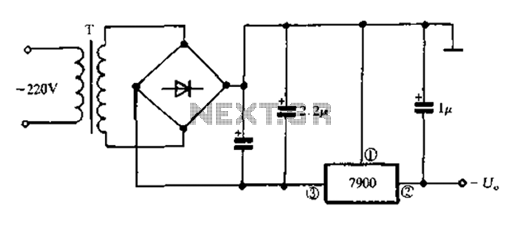
7900 series three-terminal fixed negative output voltage regulator circuit The 7900 series comprises a range of three-terminal fixed negative voltage regulators designed to provide stable output voltages. These regulators are specifically engineered to deliver a consistent output voltage, which is...
When a key is pressed, the remote control transmits a preamble followed by 32 bits of information encoded using specific pulse timings. The pulse examples can be observed in logic analyzer screen captures, although some glitches are present due...
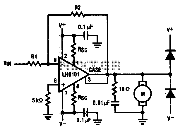
The motor driver amplifier is designed to deliver the rated current to the motor. It is important to manage power dissipation to remain within allowable limits. This precision speed regulation circuit utilizes rate feedback to maintain a constant motor...
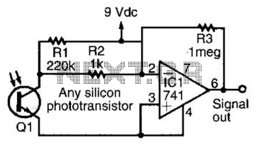
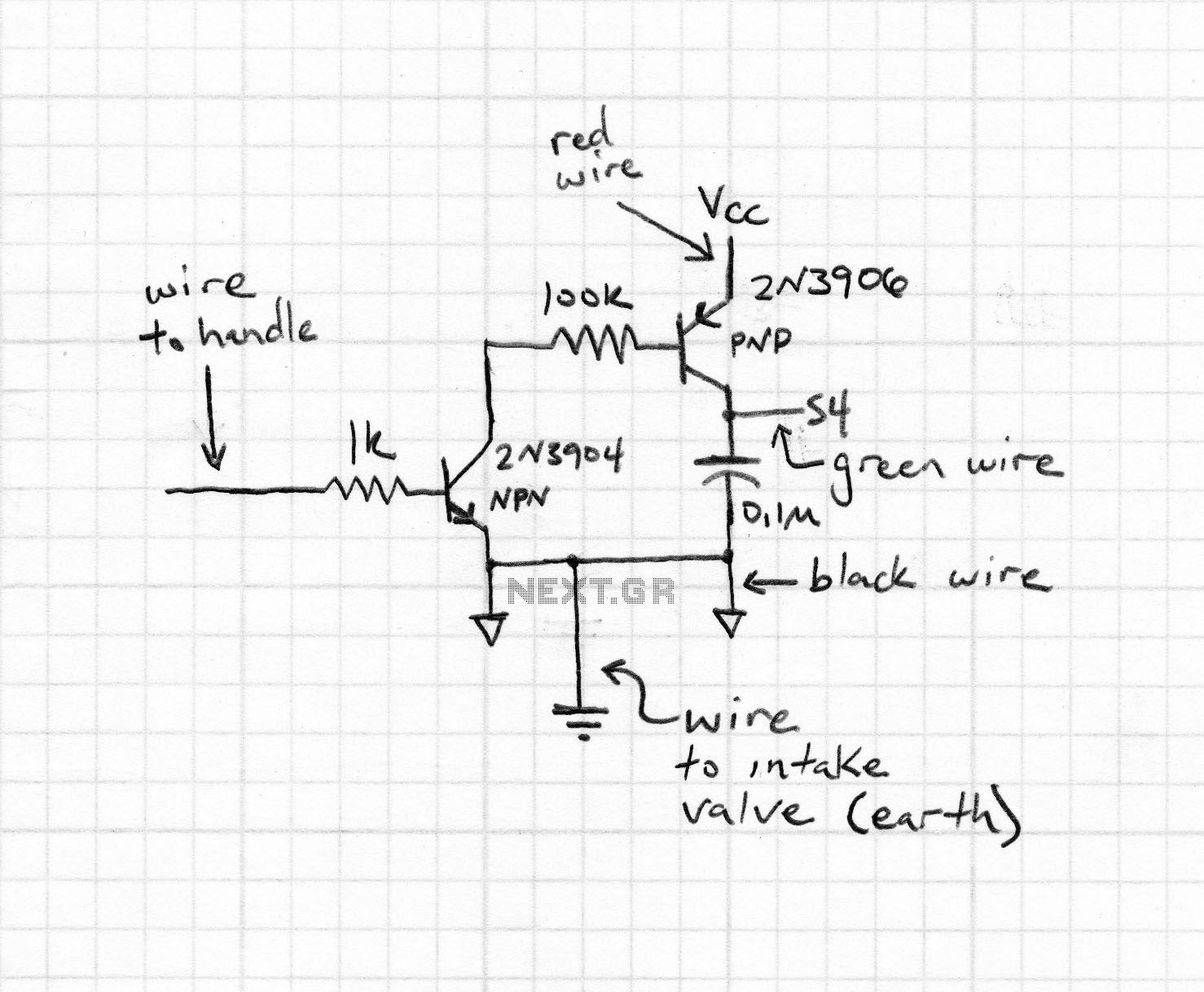
This simple amplifier is compatible with nearly any phototransistor. Although the 741 operational amplifier is designed for use with a split supply, it can also function effectively with a single-sided supply. The described amplifier circuit utilizes the 741 operational amplifier...
When working with these circuits, a light meter was purchased to eliminate the uncertainty in assessing light levels, as the human eye is not very reliable for this purpose. In electronic circuit design, particularly when dealing with light-sensitive applications, the...
Faulty readings from the DS18B20 temperature sensors used in tank thermometers were likely caused by the waterproofing method involving heat shrink and silicone. This situation provided an opportunity to enhance the code for better tolerance against erroneous readings. The...
Warning: include(partials/cookie-banner.php): Failed to open stream: Permission denied in /var/www/html/nextgr/view-circuit.php on line 713
Warning: include(): Failed opening 'partials/cookie-banner.php' for inclusion (include_path='.:/usr/share/php') in /var/www/html/nextgr/view-circuit.php on line 713