
Xbee Wireless Servo Motor Control Circuit
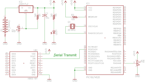
The transmitter circuit consists of a PIC microcontroller that utilizes a trimpot to provide an adjustable voltage input to its analog-to-digital (A/D) converter on pin RA0. The trimpot is configured such that its outer pins are connected to the power supply and ground, while the central pin outputs a variable voltage based on the trimpot's position. The A/D converter digitizes this voltage into an integer value ranging from 0 to 50. This digitized value is then transmitted via the PIC's UART (Universal Asynchronous Receiver-Transmitter) at a baud rate of 9600 BPS to the Din pin of the Xbee module, which is responsible for wireless communication.
On the receiving end, the Xbee module captures the transmitted data through its Dout pin, which is directly connected to the Rx pin of another PIC microcontroller. The receiving PIC decodes the incoming serial data and translates it into movement coordinates for a servo motor. The integer value received is utilized to adjust the PWM signal that controls the position of the servo motor, enabling precise movement based on the input from the trimpot.
The design allows for seamless communication between the transmitter and receiver using Xbee modules, which are known for their robust wireless capabilities. The automatic connection feature of the Xbee ensures that once powered on, the receiver will initiate communication with the transmitter without requiring additional configuration. This setup is ideal for applications requiring remote control of servo motors based on variable input signals.There are two schematics that we`ll look at to see how to build this transmitter/receiver system. The first one is the transmitter, with a variable trimpot input into RA0. The trimpot value will be sent out of the Tx pin of the PIC and to the Din pin of the Xbee module to send the signal wirelessly. The receiver circuit, will receieve the transmitted signal through the Xbee module, out of the Dout pin and to the PIC`s Rx pin. The receiving PIC will then translate the data to movement coordinates for the servo motor. The input we will give to the PIC`s will come from a standard trimpot`s output. The trimpot is tied to power and ground, with the middle pin being a variable voltage send to the PIC`s A/D converter on pin RA0. The PIC will then translate this input to an integer of value 0-50 and send it via the PIC`s serial communication module at 9600 BPS to the Xbee`s Din pin.
After the serial data is receieved by the PIC, it will put the dynamic integer value into the the delay cycle that is creating a PWM output to control the servo motor. Each specific value of 0 to 50 correlates to a specific location that the motor can move to. The Xbee receiver will automatically connect with the transmitter and begin receiving data. All data will be receiving and output via the Dout pin on the Xbee module. The Dout pin is conneceted directly to the PIC`s Rx pin so that the PIC can catch the data. 🔗 External reference
Related Circuits
H-Bridge circuit utilizing transistors for the bidirectional control of a DC motor. Integrated circuits (ICs) containing H-Bridges are employed to simplify the drive circuit. The L293D is a dual H-Bridge motor driver, allowing for the control of two DC...
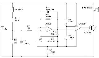
When the switch is pressed, capacitor C3 charges through resistor R4 with a time constant of 0.47 seconds. Upon releasing the switch, C3 discharges more slowly through resistors R7 and R3, with a time constant of approximately 5 seconds....
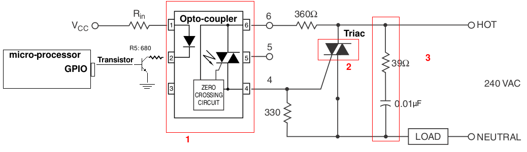
A light-dimming control system is being developed for a 240V heat lamp with a power dissipation of approximately 250W. The objective is to adjust the heat output of the lamp using control from a microprocessor. The development is based...
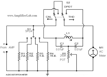
A circuit diagram of an audio distortion meter is presented here. An audio distortion meter is utilized to measure Total Harmonic Distortion (THD). The audio distortion meter is an essential tool in audio engineering, designed to quantify the level of...
The LM1036 is a DC-controlled circuit designed for tone adjustment (bass/treble), volume control, and balance. It is suitable for use in car radios, televisions, and audio systems. The circuit also incorporates loudness compensation. The LM1036 integrates several functionalities essential for...
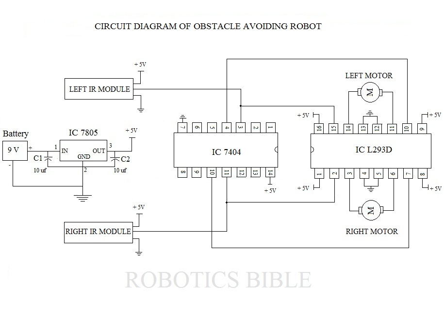
An obstacle-avoiding robot is an intelligent device that can automatically sense and navigate around obstacles in its path. It is designed without a microcontroller to simplify the circuitry and programming requirements. Understanding the circuit diagram is essential for constructing...
Warning: include(partials/cookie-banner.php): Failed to open stream: Permission denied in /var/www/html/nextgr/view-circuit.php on line 713
Warning: include(): Failed opening 'partials/cookie-banner.php' for inclusion (include_path='.:/usr/share/php') in /var/www/html/nextgr/view-circuit.php on line 713