
electronic timer with display circuit

The circuit employs the ICM7217, a versatile integrated circuit designed for digital timekeeping applications. The CMOS architecture allows for low power consumption and reliable operation. The four-digit display outputs the time in either minutes or seconds, depending on the configuration selected via switch S4.
The clock generator, IC3, is critical for providing a consistent timing reference, operating at a one-second interval. This clock signal can be further processed by IC4, which divides the frequency for applications that require longer time intervals, such as timing events that exceed one hour. The reset function is implemented through the combination of R9 and C5, ensuring that the circuit initializes correctly whenever power is applied.
The configuration of switches S7 to S10 allows for user interaction with the display, enabling the setting of countdown values. The ability to store and adjust these values enhances the circuit's functionality, making it suitable for various timing applications. The countdown feature is initiated by switch S2, which triggers the ICM7217C to decrement the displayed value. The buzzer serves as an alert mechanism, providing an audible signal when the countdown reaches the predetermined threshold of 20.00, thus signaling the completion of the timing cycle.
Overall, this circuit design showcases an efficient use of integrated circuits and user interface components to create a practical and user-friendly timing solution.The circuit is built using ICM7217 integrated circuit, manufactured by Intersil, which contains a CMOS counter up / down, with 4 digits and display properly. IC3 is the clock generator circuit which provides a square wave with period 1 s clock signal is available on pin 3 (Q13).
It can be divided by 60 in IC4, if necessary, measurement of longer t han one hour. When S6 is closed, power is connected and IC1 is reset by R9 and C5. S4`s position determine if minutes or seconds are counted: not exceeding 59 h and 59 min (position 2) or 59 min and 59 s (position 1). Miniature switches S10 S7 adjusts the display to indicate 20. 00. In a short press of S3, this choice is stored by IC1. After that, S7-S10 is adjusted so that the display to indicate 35. 00. Meanwhile, S1 must be open. Pressing S2 cause of integrative ICM7217C start counting backwards, starting from 35. 00. When the display shows 20. 00, buzzer sounds shorter. 🔗 External reference
Related Circuits
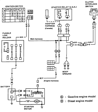
Nissan Sentra 1.6 Liter Manual Transmission Starter Circuit Wiring Diagram. The Nissan Sentra 1.6 Liter manual transmission starter circuit wiring diagram provides a visual representation of the electrical connections involved in the starting system of the vehicle. This diagram is...
An accurate phase shift of 90 degrees can be achieved using a variable resistor (VR) and an operational amplifier (op-amp). The adjustment allows for a specific frequency to be manipulated. The phase shift can range from 180 degrees to...
The circuit utilizes a 555 timer along with resistors R4, R5, and capacitor C1 configured in a controllable multivibrator mode. This setup forces the reset terminal (pin 4) to a specific state, allowing for control of the external logic...
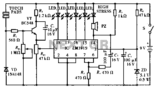
The circuit operates by utilizing two self-test table contact pads that detect electric pressure changes across the skin. The input voltage is 5 volts, which can drive up to 10 LEDs (the current configuration includes only 5 LEDs). When...

This circuit is designed for tone control utilizing a three-band equalizer. It is based on the LF351 single-chip operational amplifiers. The circuit features three adjustable ranges: bass, mid, and treble controls. The equalizer allows for approximately +/-20 dB of...
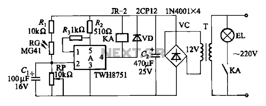
The adjustment potentiometer RP can modify the sensitivity of the device. Capacitors C1 function as an anti-light interference mechanism for instantaneous action. The adjustment potentiometer (RP) is a variable resistor that allows for fine-tuning of the device's sensitivity. By altering...
Warning: include(partials/cookie-banner.php): Failed to open stream: Permission denied in /var/www/html/nextgr/view-circuit.php on line 713
Warning: include(): Failed opening 'partials/cookie-banner.php' for inclusion (include_path='.:/usr/share/php') in /var/www/html/nextgr/view-circuit.php on line 713