
MOSFET Toggle Switching circuit
When a switch is closed, the 1uF cap voltage is connected to the junction of the 220 ohm and 33K resistors causing the circuit to change state. When the switch is opened, the cap charges or discharges to the new level through the 1M resistor, and the circuit is ready to toggle again in about 1 second. It takes a little time for the cap to move to the new level, either +V or ground.
The (0.1uF) capacitor at the transistor base was added to suppress noise that might cause false triggering if the switches are located far away from the circuit. The circuit was tested using a 12 volt, 25 watt automotive lamp, and IRFZ44. Other MOSFETs can probably be used.
The described circuit functions as a toggle switch mechanism using momentary push buttons or normally open (N/O) switches to control a load from multiple locations. The design is reliant on a debouncing method to ensure stable operation, eliminating the potential for false triggering that can occur from mechanical switch bounce. The inclusion of the 10K resistor, 10µF capacitor, and a diode on the left side of the schematic plays a critical role in establishing the initial state of the circuit upon power-up. This configuration ensures that the load is off and the NPN transistor is in a conducting state, allowing for a predictable startup behavior.
Upon activation of any switch, the voltage across the 1µF capacitor influences the junction of the 220-ohm and 33K resistors, effectively toggling the state of the output. The design also incorporates a 1M resistor that allows the capacitor to charge or discharge, setting the timing for how quickly the circuit can be toggled again. This timing is approximately one second, providing a buffer to prevent rapid switching that could lead to erratic behavior.
The addition of a 0.1µF capacitor at the base of the NPN transistor serves as a noise suppression element, which is particularly beneficial in scenarios where the switches are located at a distance from the circuit. This helps to stabilize the control signal and prevent unintended toggling due to electromagnetic interference or other noise sources.
The circuit has been successfully tested with a 12-volt automotive lamp rated at 25 watts, utilizing an IRFZ44 MOSFET for load switching. The flexibility of the design allows for the substitution of other MOSFETs, provided they meet the necessary specifications for the application. Overall, this circuit provides a robust solution for remote load control with reliable toggling capabilities.This circuit was adapted from the "Toggle Switch Debounced Pushbutton" by John Lundgren. It is useful where the load needs to be switched on from one location and switched off from another. Any number of momentary (N/O) switches or push buttons can be connected in parallel. The combination (10K, 10uF and diode) on the left side of the schematic insures the circuit powers up with the load turned off and the NPN transistor conducting. These components can be omitted if the initial power-on condition is not an issue. When a switch is closed, the 1uF cap voltage is connected to the junction of the 220 ohm and 33K resistors causing the circuit to change state. When the switch is opened, the cap charges or discharges to the new level through the 1M resistor, and the circuit is ready to toggle again in about 1 second.
It takes a little time for the cap to move to the new level, either +V or ground. The (0.1uF) capacitor at the transistor base was added to supress noise that might cause false triggering if the switches are located far away from the circuit. The circuit was tested using a 12 volt, 25 watt automotive lamp, and IRFZ44. Other MOSFETs can probably be used. 🔗 External reference
Related Circuits

This sensitive FM radio tuner is an ideal circuit for hobbyists who wish to construct their own tuners rather than purchasing a pre-assembled product. The FM radio tuner circuit is designed to receive frequency modulation signals, providing a clear and...
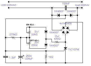
The circuit shown will switch on and off a resistive or inductive load up to 800VA with the possibility to adjust both the on and off period. Switching takes place during the zero crossing of the sine wave. The...
The American Electrician describes a glass battery jar measuring six inches by eight inches, wound with 60 to 80 turns of American wire gauge No. 18 B & S magnet wire. Inside this jar is a primary winding consisting...
The two circuits below illustrate the application of the 555 timer to activate a relay for a specified duration by pressing a momentary normally open (N/O) push button. The circuit on the left can be used for longer time...

To invoke the Spectrum +3 diagnostic routines, first reset the machine while holding the BREAK key down. This will bring up the test card display. Next, hold down the QAZMLP keys for a few seconds until the diagnostic title...
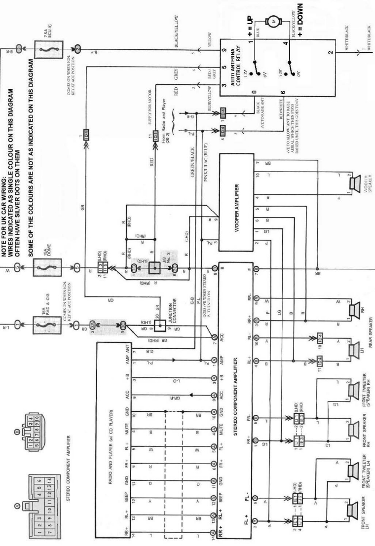
The following circuit illustrates an electrical circuit diagram for the MR2 MKII electric aerial. Features include control by an Aerial Control Relay, which consists of... The MR2 MKII electric aerial circuit is designed to facilitate the automatic operation of the...