
Limited TV channels to increase reception circuit
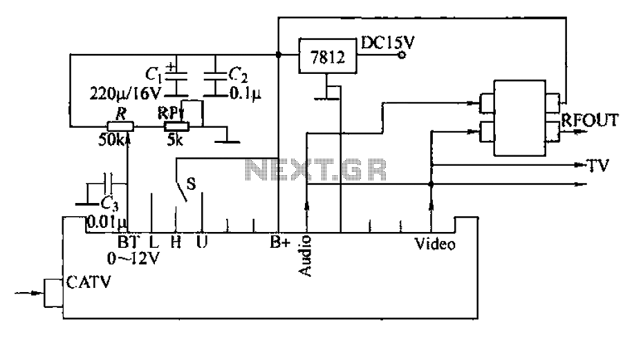
The circuit described is designed for the reception and modulation of CATV signals, integrating an electronic tuner and a modulator for seamless output to a television. The electronic tuner acts as the primary interface for capturing full-channel CATV signals, processing them into usable audio and video outputs. The audio output is designated as 'Audio', while the video output is labeled 'Vttko'.
The signal modulator plays a crucial role in this setup, as it takes the processed audio and video signals and modulates them onto a specific television channel, enabling the viewer to access additional programming without the need for complex adjustments. The direct connection of the audio and video outputs to the television's input ports simplifies the user experience, allowing for straightforward integration into existing setups.
The circuit schematic, as referenced in Figure 1-41, is tailored for S-band selection, indicating its operational frequency range. The inclusion of an RP component facilitates the selection process, allowing users to choose the desired frequency or channel with ease.
Power management within the circuit is handled by a 7812 three-terminal voltage regulator, which is responsible for supplying a stable +12V output. This voltage is essential for powering the high-frequency head and the demodulator, ensuring that the circuit operates efficiently and reliably. The use of a three-terminal regulator simplifies the power supply design while providing consistent performance across the circuit's components.
Overall, this circuit design exemplifies an effective approach to integrating CATV signal reception and modulation, providing users with a reliable and user-friendly solution for enhanced television viewing experiences. Circuit uses two features: one is the integrated electronic tuner with AV output (commonly known as the tuner) which can be received CATV full channel TV signal into a final vi deo (Vttko) and an audio signal (Audio )} another component is a signal modulator (radio modulation device), it may sound, - video signal is modulated onto a TV channel by the television viewing additional channel program. Opponents audio and video input port of the TV, you can not shoot adjuster, directly connected to the sound tuner, video output.
Circuit shown in Figure 1-41, S-band for the death choice. RP thrown in selection. 7812 three-terminal regulator generates + 12V voltage supply respectively high frequency head and demodulator shot.
Related Circuits
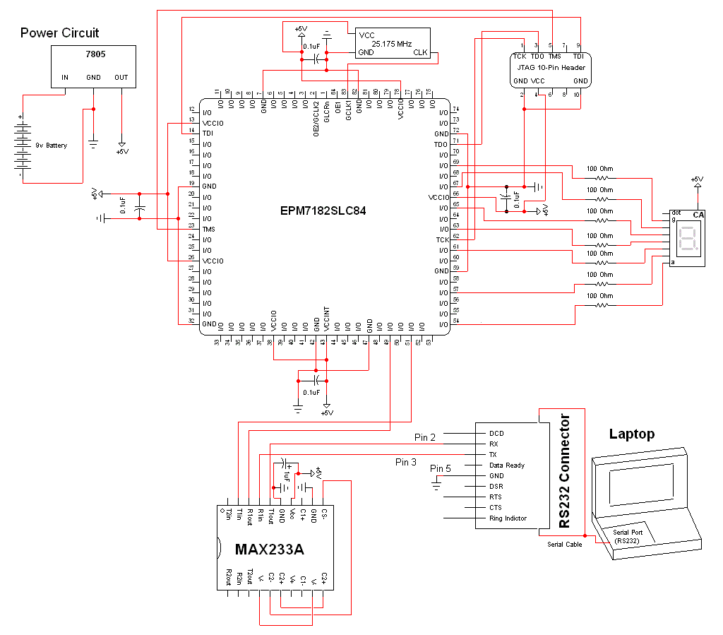
The schematic for this project is a modified version of the CPLD development board schematic. Several new components have been added for this project, and the completed schematic can be viewed below. The main components in the schematic are...
An inverter is introduced which primarily utilizes a MOS field-effect transistor in conjunction with a conventional power transformer. The output power of the inverter is determined by the specifications of both the MOS field-effect transistor and the transformer, thereby...
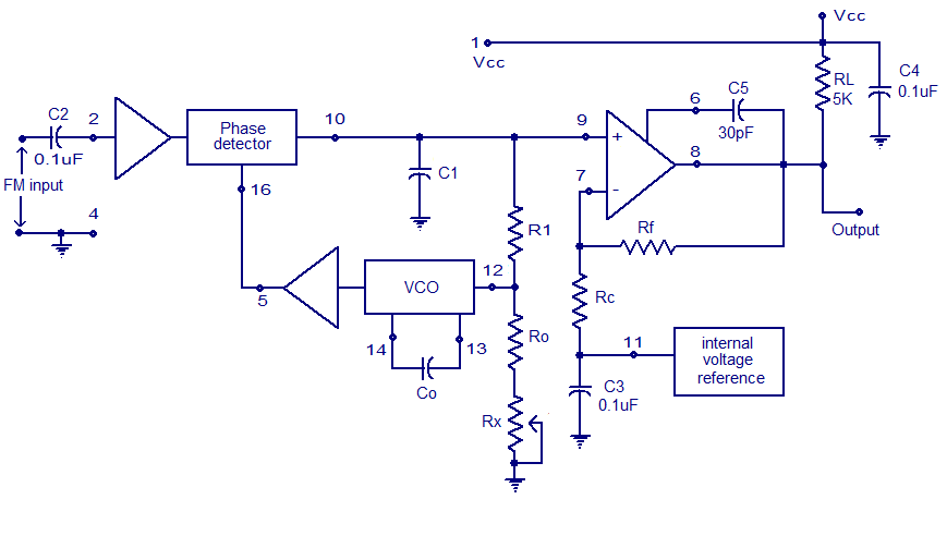
A simple PLL FM demodulator circuit using the IC XR2212 is presented. The XR2212 is a highly stable, monolithic PLL (phase-locked loop) IC specifically designed for communication and control system applications. It operates within a frequency range of 0.01...

The servo motor is a type of traditional motor that serves as the execution component in automated devices. Its most significant characteristic is its controllability; when a control signal is applied, the servo motor rotates, with its speed being...
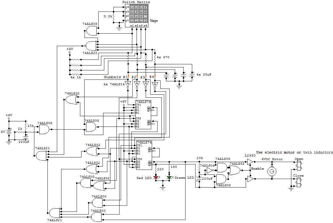
This circuit is an electronic locker controlled by a combination of switches (a code). It features a switch matrix located on the locker door, consisting of a unit of switches arranged in four rows and four columns, totaling eight...
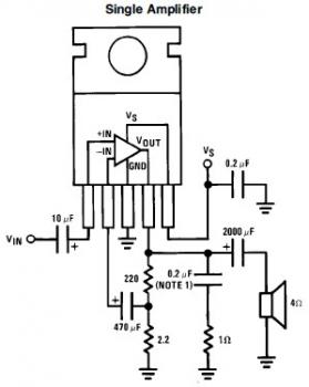
This is a simple mini audio amplifier circuit built around a single LM383 integrated circuit, along with several discrete components to support its operation. The circuit is capable of delivering approximately 7W of audio output. It can be constructed...
Warning: include(partials/cookie-banner.php): Failed to open stream: Permission denied in /var/www/html/nextgr/view-circuit.php on line 713
Warning: include(): Failed opening 'partials/cookie-banner.php' for inclusion (include_path='.:/usr/share/php') in /var/www/html/nextgr/view-circuit.php on line 713