
Agricultural harvester warehouse full schematic reminder
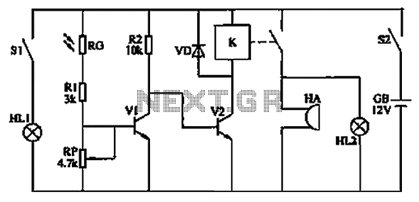
When the grain storage is full, RG receives external light, resulting in a low resistance state, causing V1 to conduct while V2 remains off. In this state, relay K is released, so HL2 remains unlit and HA does not sound. Conversely, when the grain storage is filled, it obstructs RG, leading to a high impedance state due to the lack of light, which activates V1 and V2, causing relay K to engage its normally open contact, illuminating HL2 and sounding HA to notify the operator that the grain storage is full. During nighttime operations, if external light levels are too low, S1 should be engaged to illuminate HL1, preventing the alarm system from failing. The sensitivity of the light control can be adjusted by varying the resistance of RP.
For component selection, R1 and R2 should be 1/4W metal film or carbon film resistors. The potentiometer RP must be a small synthetic membrane variable resistor. The photoresistor RG should be from the MG45 series, with a light resistance of less than 5 kΩ and a dark resistance greater than 5 MΩ. The diode VD should be a 1N4007 silicon rectifier diode. Transistors V1 and V2 can be either 58050 or C8050, or 3DG8050 silicon NPN types. HL1 should be a 12V vehicle light bulb, while HL2 should be a 12V red indicator light. Relay K must be a small 12V DC relay, and HA should be a 12V buzzer. S1 and S2 should be small toggle switches. The system can be powered by a small 12V maintenance-free battery or a 12V DC power supply sourced from the harvester.
This detailed schematic description provides a comprehensive overview of the circuit's functionality, component selection, and operational parameters, ensuring an effective and reliable grain storage reminder system. Circuit works The harvester warehouse full of reminders by the photodetector amplifier circuit and sound and light alarm circuit, as shown in Figure 1. Circuit, the photodetect or amplifier circuit by a pilot light HL1, light switch S1, photoresistor RG, resistors R1, R2, potentiometer RP and a transistor v1 composition; sound and light alarm circuit by the transistor V2, relay K, diode VD, instructions H L2 lamp and buzzer HA composition. When used, the reminder circuit mounted in a small control box, RG, HL mounted on the front panel of the control box, S1, S2 and HA mounted in the control box on the rear panel, HL2 installed local staff readily observable.
On the front side of Grain Storage combine a rectangular open slot for installation of the control box. When installed, the front panel of the control box should be installed on the inside of the storage silos, the driver in front of the rear panel.
When the reservoir within the granary full of grain warehouses, RG irradiated external light and the low resistance state, this time V1 conduction, V2 end, K is the release state, HL2 does not shine, HA is not sound. When filled with food warehouse, the warehouse of food will cover the RG, RG because no light irradiation becomes high impedance state, so that V1 end, V2 conduction, K pull its normally open contact connected, H L2 point bright, HA alarm sound to inform the driver granary is full.
When night operations, external ambient light is too dark, then S1 should be connected, so HLl lit, failure to prevent the alarm device. Adjust the resistance of RP, you can change the light control sensitivity. Component selection R1 and R2 use 1/4W metal film resistor or a carbon film resistors. RP use of small synthetic membrane variable resistor. RG choose M G45 series (light resistance less than 5kfl, dark resistance is greater than 5 MfZ) photosensitive resistor.
VD choose 1 N4007 type silicon rectifier diodes. V1 and V2 use 58050 or C8050,3 DG8050 silicon NPN transistors. HL1 selection of vehicles with 12V light bulb; HL2 selected 12V red light. K small 12V DC relay selection. HA selects sound source 12V comes with a buzzer. S1 and S2 use a small toggle switch. GB using a small 12V maintenance-free battery or a 12V DC power supply on the harvester.
Related Circuits
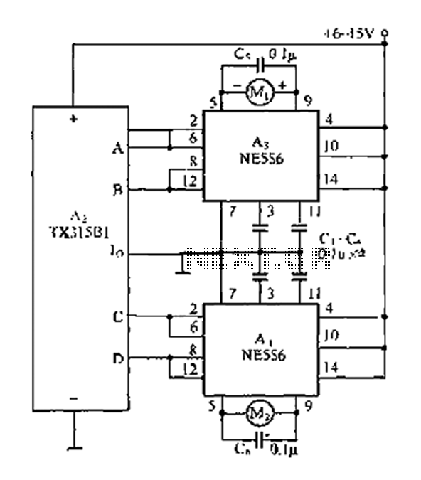
The travel remote control model is represented by a circuit diagram. The NE556 is a dual time base IC that includes two separate circuits, each consisting of a Schmitt trigger circuit. The output control is achieved through the TX315B1,...
To construct the circuit, follow the provided schematic. If assistance is required, do not hesitate to reach out for support. If there are difficulties in identifying the components... To build the circuit effectively, it is essential to adhere closely to...
Mobile phone battery chargers available in local markets can be quite expensive. The circuit presented here offers a low-cost alternative for charging cellular phone batteries or battery packs with a rating of 7.2 volts. This low-cost phone battery charger circuit...
A common issue encountered is that individuals possess a schematic, also known as a circuit diagram, that they wish to construct. However, they discover that there are... Building a circuit from a schematic requires a clear understanding of the components...
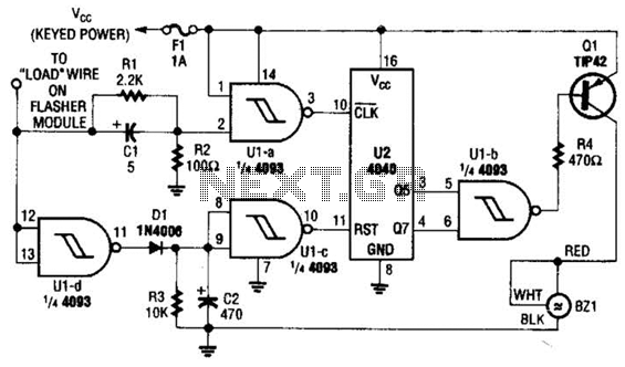
This circuit counts the flashes of turn signals. After approximately 70 flashes, a chime sounds to remind the driver to deactivate the turn signal. The period can be altered by using different taps on U2 if desired. BZ1 serves...
Blue VALUES replaced by values in RED. Blue COMPONENTS removed from circuit. Red components added to circuit. More: Optional: move relay mute contacts to other side of C21. The provided description indicates modifications to an existing electronic circuit. The changes...