
Building a device from a schematic
Building a circuit from a schematic requires a clear understanding of the components involved and their interconnections. A schematic diagram serves as a blueprint, providing essential information about the electrical connections and functionality of the circuit. Each symbol in the schematic represents a specific electronic component, such as resistors, capacitors, transistors, and integrated circuits.
To successfully construct a circuit from a schematic, one must first identify all components listed in the diagram. This includes verifying the values of resistors, the capacitance of capacitors, and the specifications of any active components. It is also crucial to understand the power supply requirements, including voltage and current ratings, to ensure that the circuit operates correctly.
Next, the physical layout of the components on a breadboard or printed circuit board (PCB) should be planned. Proper placement can help minimize noise and interference, as well as facilitate easier troubleshooting later on. Following the schematic, connections between components should be made using appropriate wiring techniques to ensure reliable electrical contact.
Testing the circuit after assembly is a critical step. This involves using a multimeter to check for continuity in the connections and measuring voltages at various points to confirm that the circuit behaves as expected. If discrepancies arise, the schematic should be referenced to identify and rectify any errors in connections or component values.
In summary, constructing a circuit from a schematic requires careful attention to detail, a thorough understanding of electronic components, and systematic testing to ensure functionality.A problem we see a lot is that people have a schematic (otherwise knows as a circuit diagram) that they want to build. But they find there are.. 🔗 External reference
Related Circuits
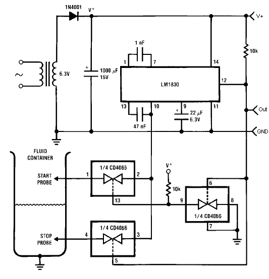
The LM1830 fluid level detector circuit is a device designed to indicate the presence or absence of aqueous solutions. It features a low external parts count, a wide operating supply range, an internally regulated supply, and AC or DC...
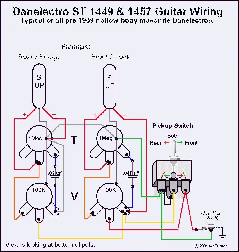
Using a magnetic compass, ensure that both pickups have a South polarity on the top of each pickup. Verify this by checking for a North polarity on the bottom of the pickups. It is uncommon to find both pickups...
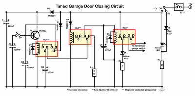
Timer garage door circuit schematic diagram, printed circuit board. The timer garage door circuit is designed to automate the opening and closing of a garage door based on a predetermined time interval. The schematic diagram illustrates the layout and connections...
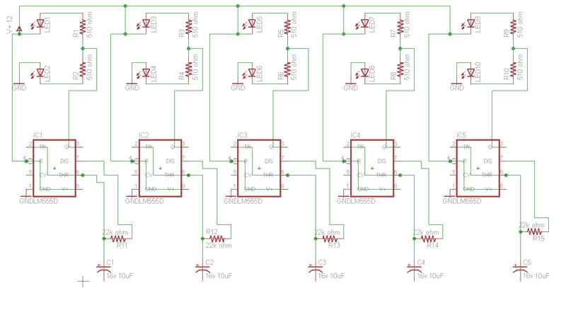
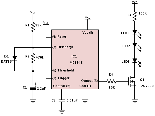
Build a circuit that will flash five pairs of LEDs at variable rates. To achieve this, a circuit utilizing five NE555 timers has been designed. Trim pots will be used to control the variable flash rate. Assistance is needed...
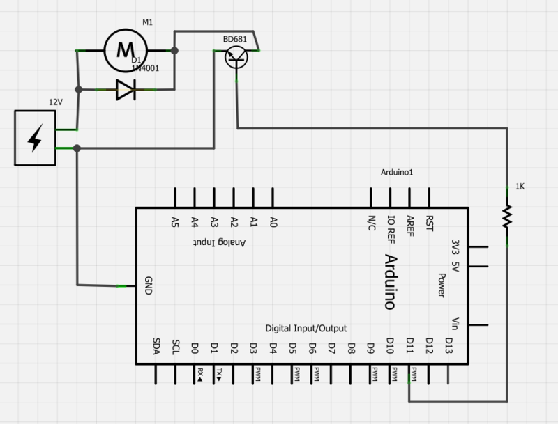
Power a 12V fan using a Darlington transistor to control the speed from an Arduino. When wired as described, nothing happens even though a PWM signal is being sent. It is suggested to edit the question and ensure the...
This precise one-pulse-per-second clock is constructed using a few common components and is driven by a 50 or 60 Hertz mains supply without a direct connection to it. An audible beep or a metronome-like click, along with a visible...