
Perfboard Hackduino Arduino-compatible circuit
The ATMega microcontroller serves as the central processing unit for various electronic projects, particularly in embedded systems. When working with the ATMega168 or ATMega328, the integration of an Arduino bootloader simplifies programming and facilitates the use of the Arduino IDE for development. The choice between bootloaded and unbootloaded chips can significantly impact the initial setup cost and flexibility in programming.
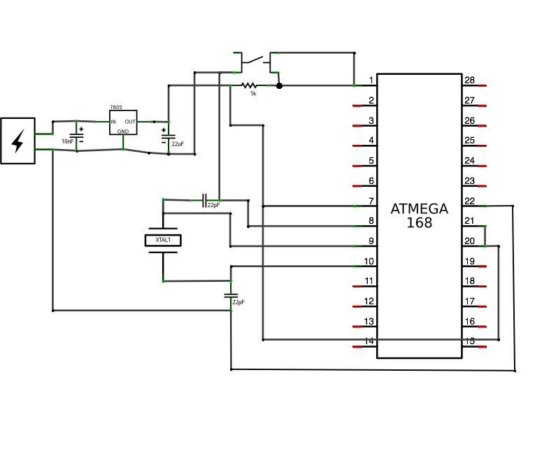
The voltage regulator component in this circuit, the LM7805, is a linear voltage regulator that provides a stable 5V output necessary for the operation of the ATMega microcontroller. The regulator's input can accept a voltage range of 7V to 35V, making it versatile for different power sources. The 10nF capacitor connected to the output helps filter high-frequency noise, ensuring a clean power supply to the microcontroller.
When designing the circuit layout, it is critical to allocate sufficient space for the components, particularly the voltage regulator and any additional capacitors or filters that may be required. Proper orientation of the IC socket is vital; the notch must align with the designated pin one on the board to prevent damage to the microcontroller during installation.
In summary, this project outlines the foundational steps to create a functional circuit using the ATMega microcontroller, emphasizing careful planning of the layout and component selection to ensure a reliable and efficient electronic assembly.ATMega168 or 328microcontroller chip w/Arduino bootloader (you can use the one on your Arduino for now!) $4. 00-$5. 50 - buy unbootloaded mouser (cheaper) / buy bootloaded sparkfun (expensive) I have created a Mouser project that includes everything you will need, except for the perfboard itself(Mouser doesn`t carry a good one at a good price).
Al so, this is the blank ATMega328- so you will need to bootload the chip yourself. Also keep in mind that ordering in multiples makes everything cheaper! Here is the Mouser project. First step is to figure out what exactly what you are putting into this circuit. For this tutorial all we will build, other than the ATMega necessities, is a voltage regulator, so I am leaving space at the top of the board for this. I also recommend leaving some space towards the bottom for a capacitor. However, if you know this will include much more than just the ATMega circuit, you should plan this out on your board now, and install the IC socket appropriately.
Most IC`s (Integrated Circuits), and consequently their corresponding sockets, have a notch on one end. In this photo, you`ll see the notch is towards the top of the board. This is extremely important to pay attention to both while building the circuit and when inserting the chip during the last step.
LM7805 circuit goes next. The 7805 allows you to power the circuit with a 9v battery or even 12v DC power supply, and ouputs 5v which is what our chip wants. With the chair facing you, solder the 10nF capacitor connecting the right two legs of the 7805. In this position, from left to right, the pins areinput voltage-ground-output voltage(5v). 🔗 External reference
Related Circuits
A simple preamplifier circuit is often required, utilizing a few components for ease of construction. This circuit employs an operational amplifier, specifically the Motorola TCA5550, which features a dual amplifier configuration. It provides outputs for adjusting volume, balance, treble,...
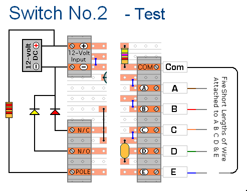
The prototype of Keypad Switch No. 2 was constructed using only the stripboard layout as a reference. If the layout has been accurately reproduced, a functional circuit will result. Once the layout is confirmed to be correct and a...
This digital thermometer circuit diagram utilizes a standard 1N4148 diode as the temperature sensor. The temperature coefficient of the diode is -2 mV/°C. The digital thermometer circuit leverages the characteristics of the 1N4148 diode, which exhibits a predictable voltage drop...
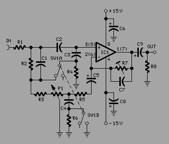
To achieve optimal audio reproduction at various listening levels, it is essential to incorporate tone-setting controls that align with the well-documented characteristics of human auditory perception. Specifically, human ear sensitivity exhibits a non-linear response across the audible frequency spectrum,...
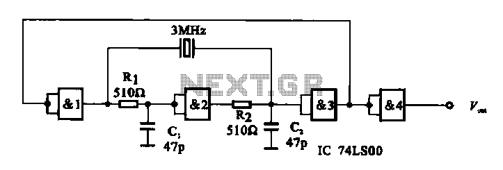
A crystal oscillator circuit is composed of several gates. Figure (A) illustrates a crystal oscillator circuit operating at 1 MHz, while Figure (B) depicts a 20 MHz crystal oscillator circuit. Figure (C) represents a variable crystal oscillator circuit with...
This circuit provides a simple visual indication of audio level signals, adaptable to various user requirements. It can be configured for different input levels, which can be adjusted using trimmer potentiometers TR1 (state) and TR2 (gain). The audio signals...
Warning: include(partials/cookie-banner.php): Failed to open stream: Permission denied in /var/www/html/nextgr/view-circuit.php on line 713
Warning: include(): Failed opening 'partials/cookie-banner.php' for inclusion (include_path='.:/usr/share/php') in /var/www/html/nextgr/view-circuit.php on line 713