
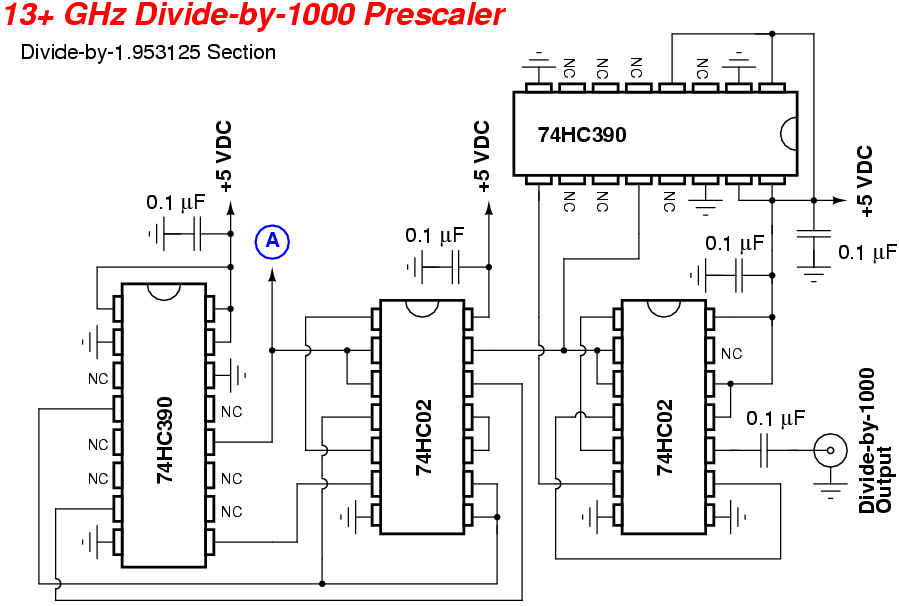
0.1 - 3.5GHz Prescaler

The prescaler circuit consists of several key components, including a high-frequency input stage, a frequency division stage, and an output stage. The input stage is typically designed to accommodate high-frequency signals, ensuring that the circuit can effectively process signals up to 3.5 GHz. This may involve the use of RF amplifiers or impedance matching networks to optimize signal fidelity.
The frequency division is achieved through a combination of flip-flops or counters that are configured to divide the input frequency by 1000. For instance, a series of binary counters can be employed, where each stage divides the frequency by 2, ultimately achieving the desired division ratio. The choice of components in this stage is critical, as they must operate efficiently at high frequencies while maintaining low phase noise and minimal signal distortion.
The output stage is responsible for converting the divided frequency output into a format suitable for measurement. This may involve additional filtering to remove harmonics and noise, ensuring that the output signal is clean and stable. The final output frequency of 3.5 MHz can then be easily measured using standard frequency meters, making the prescaler a valuable tool in various RF applications, including communications and signal analysis.
Power supply considerations are also essential in the design of this prescaler. A stable power supply is required to ensure that the circuit operates reliably across its specified frequency range. Additionally, proper grounding and layout techniques must be employed to minimize electromagnetic interference and ensure optimal performance. Overall, the prescaler is a crucial component for frequency management in high-frequency applications.This handy prescaler divides input frequency by 1000. It takes maximum input frequency of 3. 5GHz and converts it into 3. 5MHz that may be measured using standard frequency meter. 🔗 External reference
Related Circuits
This project will describe a prescaler which will work up to 2.5GHz and with very high input sensitivity. The prescaler will divide the input frequency with either 1000 or 10.000. The divided output signal is 0/5 volt and can...
A straightforward "divide-by-1000" circuit was originally designed by Zeljko Bozic, S52ZB, in a 2006 issue of VHF Communications Magazine. This project aims to extend the range of older and more affordable frequency counters. Frequency counters capable of measuring up...
These parameters are expected with an approximately 50% square wave up to frequencies of several MHz, and symmetric sine waves at higher frequencies. The primary limitation is based on the maximum clocking rate specification for the MM74HC6040 ripple counter...
Having found a u664b prescaler chip (Telefunken) from an old TV tuner, I decided to build a valid frequency counter using PIC16F84. The prescaler I use is able to divide by 64 every frequency from 30 to 1300 MHz....
This is a beta release of the PIXpand project. The PIXpand is a device that connects to a TI calculator and enables it to store and retrieve data to and from PlayStation memory cards. A beta release has been...
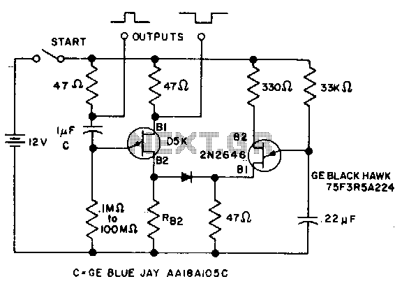
The timer interval begins when power is supplied to the circuit and ends when voltage is applied to the load. The 2N2646 transistor is utilized in the oscillator, which generates pulses to the base of the D5K. This configuration...