
Frequency prescaler for multimeter up to 2.5GHz
The prescaler circuit is designed to operate efficiently within the frequency range of 10 MHz to 2.5 GHz, providing a division factor of either 1000 or 10,000, selectable via a jumper switch (SW1). The prescaler utilizes the LMX2322 integrated circuit, which is known for its high sensitivity and ability to handle RF signals. The input pins 7 and 8 of the LMX2322 are configured symmetrically to optimize signal reception, ensuring that the circuit can effectively process high-frequency inputs.
The input impedance of the prescaler is approximately 100 ohms. To achieve a standard 50-ohm input impedance, a resistor (R7) is incorporated into the circuit. This configuration is crucial for matching the impedance of typical RF sources, thereby minimizing reflections and ensuring maximum power transfer. The output of the prescaler, buffered by transistor Q1, delivers a TTL-level signal, allowing direct interfacing with various electronic instruments.
A critical aspect of the design is the sensitivity of the LMX2322 input. When the input is not connected, the circuit may inadvertently pick up ambient RF noise, leading to self-oscillation. This phenomenon can serve as a diagnostic tool; upon powering the circuit, a display reading of approximately 1.4-1.6 GHz indicates proper functionality of the phase-locked loop (PLL). To mitigate unwanted self-oscillation, R5 is included in the input stage, ensuring that the frequency counter displays zero when no RF signal is present. Importantly, R5 is designed not to interfere with the RF signal or the overall sensitivity of the frequency counter.
The prescaler circuit's performance has been validated through measurements, confirming its capability to accurately process VCO signals within the specified frequency range. The careful design of the input termination and impedance matching is essential for achieving optimal performance, particularly in high-frequency applications.This project will describe a prescaler which will work up to 2.5GHz and with very high input sensitivity. The prescaler will divide the input frequency with either 1000 or 10.000. The divided output signal is 0/5 volt and can be connected to your instrument as it is. The divider ration is set by a jumper (switch). A PIC 16F84 handle all communication to the prescaler. The main part of this project is the PIC16F84 and a prescaler LMX2322. The input of the LMX2322 is symmetrically at pin 7 and 8. The input impedance is about 100 ohm and with R7 you form an input impedance of 50 ohm. Transistor Q1 forms a buffer for the output frequency which is the divided signal. The output is TTL level and can be directly connected to any instrument. SW1 is the switch that set the divider ration. Before you solder R5 you should test the frequency counter. The input of the LMX2322 (prescaler) is very sensitive. When the input is not connected to any source, the circuit will pick up any RF noise and start to self oscillate. This behaviour can be used to test the circuit function in a simple way. When the power is on, the display should show something like 1.4-1.6 GHz. If so, you can be sure that the PLL is soldered correctly and working fine. To prevent self oscillation, R5 is added to the input stage. This will make the counter show 0 when no RF signal is applied. R5 will not affect RF signal or sensitivity of the frequency counter. Table below show my measurements of the sensitivity of this unit. This counter will work best when the input frequency is from 10 MHz to 2.5 GHz. Below you will see a table of some measurement I have made with an old frequency generator. I have also measured VCO:s at 2.0 -2.5 GHz perfectly. The input signal is terminated at the prescaler with 100 ohm and since the input impedance of the prescaler is 100 ohm you have a total input impedance of 50 ohm.
🔗 External reference
Related Circuits

A voltage-to-frequency converter (VFC) circuit is depicted in the schematic diagram below. The circuit utilizes a 555 integrated circuit (IC) as the core component for its operation. The voltage-to-frequency converter is a crucial component in various analog and digital...
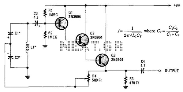
Essentially, this is a Hartley oscillator utilizing a triple-emitter follower, suitable for audio and low radio frequencies. The frequency is determined by the components, and at 1 kHz, a typical capacitor value would be 4.7 µF tantalum, although this...
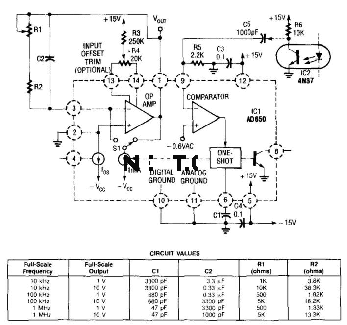
In this circuit, the input from the IC2 optocoupler is connected to the comparator input of the AD650 (Analog Devices or Maxim Electronics) voltage-to-frequency (V/F) converter. This converter internally generates a pulse that is sent to the operational amplifier,...
A voltage-to-frequency converter (VFC) circuit is illustrated in the schematic diagram below. The circuit utilizes a 555 integrated circuit (IC) as the central component of its operation. The voltage-to-frequency converter (VFC) is a crucial electronic circuit that converts an input...
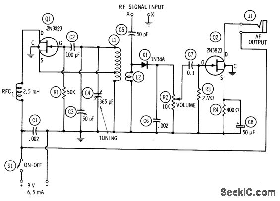
The circuit includes a 1-2 MHz oscillator (Q1), an untuned mixer (X1), and an audio frequency beat-note amplifier (Q2). Capacitor C4 is calibrated to display frequency readings directly from 1 to 2 MHz when using an accurate unmodulated RF...
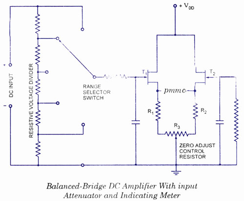
The electronic multimeter is a versatile general-purpose instrument capable of measuring both DC and AC voltages, as well as current and resistance. This solid-state device typically includes a built-in power supply for operation on AC mains and often features...
Warning: include(partials/cookie-banner.php): Failed to open stream: Permission denied in /var/www/html/nextgr/view-circuit.php on line 713
Warning: include(): Failed opening 'partials/cookie-banner.php' for inclusion (include_path='.:/usr/share/php') in /var/www/html/nextgr/view-circuit.php on line 713