
SDR TX 50MHz
The described circuit utilizes a 74AC04 inverter to generate an oscillating signal, which is crucial for achieving the desired 90-degree phase shift in VHF applications. The oscillator configuration is essential for creating a stable frequency output, where the inverter's characteristics contribute to the overall performance of the circuit. The phase shifter, composed of capacitor C5 and resistor R6, plays a pivotal role in adjusting the phase of the output signal to meet the specific requirements of the application.
To further enhance the signal, the 74HC14 is employed to convert the oscillating signal from the inverter into a square wave form. The square wave output is often preferred in digital applications due to its sharp transitions and well-defined amplitude levels, which are conducive to driving subsequent stages of a circuit with minimal distortion.
The use of the 74HCU04 in crystal oscillator circuits is common due to its ability to provide stable oscillation characteristics. However, in this instance, the 74AC04's buffer stage was found to induce parasitic oscillations that negatively impacted the circuit's performance. This observation highlights the importance of carefully selecting components based on their characteristics and interactions within the circuit.
In summary, the combination of the 74AC04 inverter, phase shifter components, and the 74HC14 provides a straightforward approach to achieving a 90-degree phase shift in VHF applications. However, careful consideration must be given to the potential for parasitic oscillations when utilizing different logic families, as evidenced by the initial testing with the 74HCU04. Proper design practices and component selection are critical for optimizing performance in such oscillator circuits.Making 90 degree phase shift on VHF. This IQ Oscillator is easy way with two logic IC`s. 74AC04 inverter is used as oscillate circuit. C5 and R6 is phase shifter. 74HC14 has a duty to convert into square-wave. It is usualy used 74HCU04 in crystal oscillator circuit. Buffer of 74AC04 cause parasitic oscillation. So I teste d with 74HCU04 first, but the result was not good for me. 🔗 External reference
Related Circuits
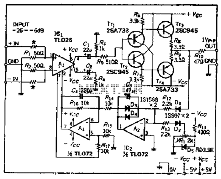
A car circuit is utilized for external voltage-controlled amplification in wideband amplifiers using the TL0216 IC. This design incorporates compression characteristics of 2dB. The input circuit consists of resistors that reduce the input level when it is between -26dB...
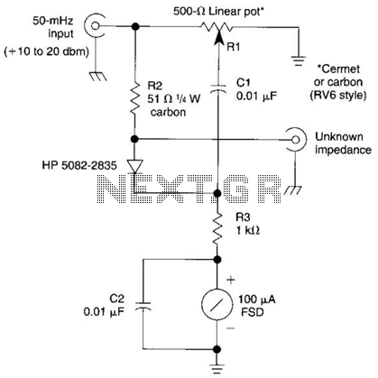
The bridge shown was used for measurements on 50-MHz amateur radio antennas. Rl is a miniature 500 linear potentiometer. The unknown impedance is compared to R2, a 51-ohm resistor. An external signal source is required. The described bridge circuit is...
The Software Defined Radio (SDR) hardware, in its most basic configuration, includes a wideband switched balanced mixer and a low noise LF amplifier. This straightforward hardware demonstrates remarkable sensitivity and linearity, making it suitable for both testing and regular...
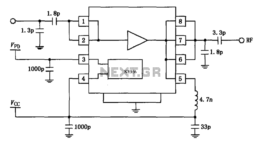
The circuit depicted in the figure is based on the RF2126, a 2450 MHz end-stage linear power amplifier. The radio frequency (RF) signal enters through input pin 1 and is subsequently amplified by the amplifier stages (pins 5, 6,...
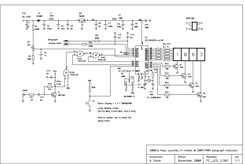
This device is an upgraded version of the PIC16C71 4-digit LED frequency counter and voltmeter. It eliminates several hard-to-find components from the previous model, which have been out of production for some time. The older PIC16C71 has been replaced...
This bugg is based on my previous 3-transistor transmitter. This bugg unit has many advantages. The transmitter uses a crystal 46.515MHz to hold a steady frequency. The frequency can be fine-tuned by some 100kHz. The transmitter can send data...
Warning: include(partials/cookie-banner.php): Failed to open stream: Permission denied in /var/www/html/nextgr/view-circuit.php on line 713
Warning: include(): Failed opening 'partials/cookie-banner.php' for inclusion (include_path='.:/usr/share/php') in /var/www/html/nextgr/view-circuit.php on line 713