
Precision Power Supply 0-40V 0-2A adjustable current limiting

The power supply consists of two main sections: the output supply section, which includes XFMR1, Br1, C1, and C2 to provide the necessary voltage and current, and the IC supply section, comprising XFMR2, Br2, and C3. These two sections must remain separate to maintain a floating ground for IC1. The voltage control is managed by RV1 and R2, which set the operating point of a constant current source at pin 3 of IC1. Adjusting RV1 establishes the maximum output voltage. Pins 8 and 9 serve as inputs to a high-gain differential amplifier within IC1. By varying potentiometer P1, the voltage at pin 8 changes, prompting the output voltage to adjust until it matches pin 8, maintaining equal voltage levels at pins 8 and 9 due to the amplifier's high gain.
The current control section utilizes pin 12 of IC1 as an internal voltage reference, working with RV2 and R3 to set the maximum output current, adjustable to a limit of 2 amps. The inputs for the current control's differential amplifier are found at pins 10 and 11 of IC1. Potentiometer P2 is used to set the maximum voltage across resistors R5 and R6 before current limiting occurs, establishing the maximum output current.
The supply operates in either constant current or constant voltage mode, determined by the outputs of the voltage and current differential amplifiers, which are fed into an OR gate. The selected output from the OR gate is available at pin 5 of IC1.
Compensation and protection circuits are implemented to enhance the power supply's reliability. Capacitor C4 is used for internal compensation of IC1, while diodes D4 and D5 protect against input voltage exceeding 0.7V. Diodes D2 and D7 safeguard the supply from potential damage when an external power supply is connected.
The output section, driven by pin 5 of IC1, activates transistor Q1, which in turn drives Q2. Q2 dissipates the majority of the power, necessitating an appropriately sized heatsink.
Utilizing a printed circuit board (PCB) is highly recommended for constructing the power supply, as it streamlines the assembly process and minimizes wiring errors. It is advisable to follow the assembly instructions sequentially. Initial steps include inspecting the PCB for oxidation on the copper traces and using fine steel wool to clean any oxidized areas. Afterward, jumper JP1 can be installed and soldered, followed by the installation of the 14-pin IC socket, ensuring correct alignment of pin 1 markings. Finally, Br1 and Br2 are soldered into place, with special care taken to maintain the correct polarity.This Precision Power Supply is a nice addition on your workbench as primary, or in my case, a supplementary power supply. With zero to 40V and 2A with adjustable current limiting it will surely gets lots of use on your bench.
On average the most amperage for a power supply someone needs is around two or three amps. The sensitivity for current limi ting is fully adjustable. Have fun building!" Test instruments are considered to be some of the most useful tools available when constructing a project. They are also considered to be the most expensive tools one could buy. For instance, a power supply of any quality and usefulness can range from several hundred dollars to several thousand dollars.
The alternative to buying a power supply is to build one. The power supply in this article has a voltage range from 0 to 40V and a current range from 0 to 2 amps with current limiting set by the user. The quality of the supply is determined by the time and care the builder takes while constructing it.
The first parts to look at are the two power supply sections. The output supply section consists of XFMR1, Br1, C1, and C2. They supply the appropriate voltage and current required at the output. The IC supply consists of XFMR2, Br2, and C3. The two power supply sections must be separate from each other because a floating ground is required for IC1. The next section is the voltage control. RV1 and R2 determine the operating point of a constant current source out of pin 3 of IC1. By varying RV1 the maximum output voltage will be set. Pins 8 and 9 are inputs to a high gain differential amplifier contained in IC1. By adjusting potentiometer P1 the voltage at pin 8 will vary; this will cause the voltage at the output to change until it is equal to the voltage at pin 8.
Due to the high gain of the differential amplifier the voltage at pins 8 and 9 will always remain equal. The current control section is next. Pin 12 of IC1 is an internal voltage reference, used with RV2 and R3 they set the maximum output current.
RV2 is adjusted to limit the maximum output current to 2 amps. The inputs to the high gain differential amplifier of the current control section are pins 10 and 11 of IC1. By adjusting potentiometer P2 the maximum voltage across R5 and R6 before current limiting are set. This voltage is proportional to the output current, therefore the maximum output current will be set.
Constant current/constant voltage is the next section to look at. The outputs from the voltage and current high gain differential amplifiers are fed through an OR gate. The output that is chosen by the OR gate will then be the output of the IC, which is at pin 5. This causes the supply to switch between the constant voltage or constant current mode. The next sections to describe are the compensation and protection circuits. C4 is used for internal compensation of IC1. D4 and D5 prevent the input voltage to the high gain differential amplifier from exceeding 0. 7V. D2 and D7 protect the supply from damage that may be caused when an external power supply is connected.
The output section is next, pin 5 is the output of IC1. This drives Q1 which inturn drives Q2. The main power dissipated by the supply will be by Q2, this is why an appropriate sized heatsink is required. The printed circuit board is highly recommended to be used when constructing the power supply, as it will save time and reduce the risk of wiring errors.
It is also recommended that the PCB be assembled in the order that the instructions are given. The first step is to check the PCB for any oxidation on the copper traces. If the copper looks oxidized, use some fine steel wool to remove it. Now JP1 can be installed and soldered in. Next is the 14 pin IC socket, making sure that the pin 1 marking on the the socket is aligned with the pin 1 marking on the PCB. Now Br1 and Br2 are soldered in place. Special care should be taken so that the positives o 🔗 External reference
Related Circuits
Features: 1.3-12.2 V, 1 A, over-current protection. This is a simple but reliable device based one of the oldest integrated voltage regulators of them all - the LM723. The LM723 voltage regulator is a versatile and widely used component in...
This application note demonstrates a simple 8-direction digital compass application utilizing Zilog's Z8 Encore!® MCU and an external compass sensor hardware. Communication ports are provided for the digital compass to receive commands and send status via the I2C bus...
This power supply unit (PSU) is specifically designed for high-current ham radio transceivers. It safely provides approximately 20 Amps at 13.8V. For lower current applications, a separate current-limiting output is available, capable of 15 mA up to a total...
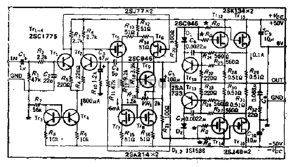
The circuit consists of three identical basic stages, with the second stage featuring a differential output from the power MOSFET, 2SJ77. A current mirror circuit utilizing 2SK214 is implemented. The operating current is 6mA; however, due to the power...
Another adjustment of application operational amplifiers to adapt a power supply is apparent below. The power supply requires an additional adjustment to supply the op-amps with a bipolar voltage (+/- 8 volts), and the negative voltage is also used...
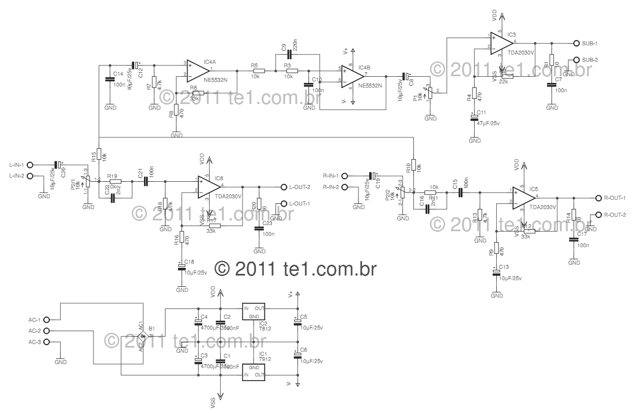
This circuit is a complete application for a 2.1 amplifier system, featuring two satellite speakers for TDA and one subwoofer. It is commonly used in commercial applications to enhance the audio output of computers using a stereo amplifier along...