
1 5 volt led flashers
The LM3909 is a specialized integrated circuit designed for driving LEDs in flashing applications. This IC allows for the creation of visually appealing light patterns with minimal external components. In the described circuit, the primary components include the LM3909 IC, a timing capacitor, and an LED, which collectively enable the flashing effect.
The 1.5-volt battery serves as the power source, providing sufficient voltage for the LM3909 to operate effectively. The timing capacitor, when connected to the LM3909, determines the flashing frequency of the LED. By selecting a capacitor of appropriate capacitance, the time interval between flashes can be adjusted, allowing for customization of the visual effect.
The LED is connected to the output pin of the LM3909, which drives the LED on and off according to the timing set by the capacitor. The circuit can be further enhanced by adding resistors to limit the current through the LED, ensuring its longevity and preventing damage.
This simple yet effective LED flasher circuit can be utilized in various applications, such as decorative lighting, indicators, and signaling devices. Its low power consumption makes it suitable for battery-operated devices, while the ease of assembly and minimal component requirements contribute to its popularity among hobbyists and engineers alike.The LED flasher circuits below operate on a single 1.5 volt battery. The circuit on the upper right uses the popular LM3909 LED flasher IC and requires only a timing capacitor and LED.. 🔗 External reference
Related Circuits

An ECU must have a way to monitor battery voltage. Here is a simple op-amp based circuit which will illuminate the LED when the battery voltage drops to a certain level. The turn-on point is set with R2. You...

This ultra-bright white LED lamp operates on 230V AC with low power consumption. It is suitable for illuminating VU meters, SWR meters, and similar applications. The cost of ultra-bright LEDs available in the market ranges from Rs 8 to...

The National LX5700 temperature transducer supplies input to a code conversion circuit that drives a 3-digit LED display. This display indicates temperatures ranging from -40°F to +100°F or -40°F to +199°F, controlled by a ganged switch. The National LX5700...

In this project, eight LEDs are connected to PORT B of a PIC microcontroller. A push-button switch is also connected to bit 0 of PORT A using a pull-up resistor. When the switch is pressed, the LEDs scroll to...

A user is utilizing YENKA software to diagram circuits but is experiencing confusion regarding the voltage calculations in a basic series circuit, as illustrated in the attached image. In a basic series circuit, components are connected end-to-end, forming a single...
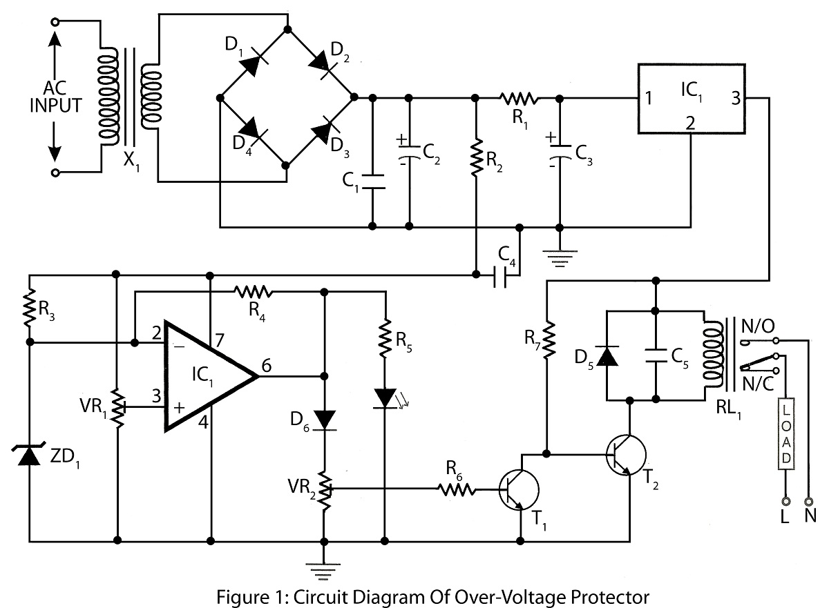
An Over Voltage Protector is a straightforward circuit designed to safeguard appliances from excessive voltage. It includes a circuit diagram and a parts list for various electronics projects related to over voltage protection. The Over Voltage Protector circuit typically employs...