
Over Voltage Protector
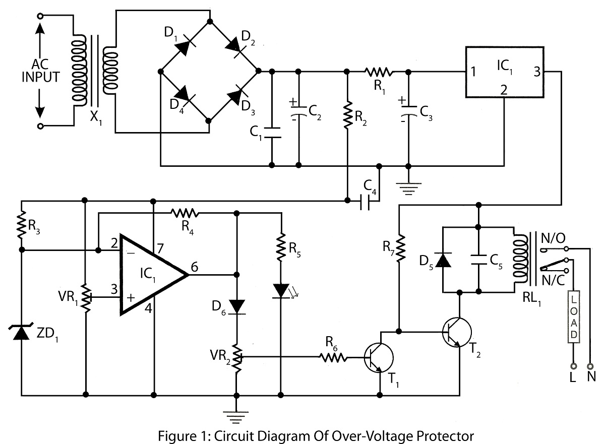
The Over Voltage Protector circuit typically employs a voltage sensing mechanism to monitor the input voltage level. When the voltage exceeds a predetermined threshold, the circuit activates protective measures to prevent damage to connected appliances.
Key components often included in this circuit are:
1. **Voltage Sensor**: This component detects the input voltage and triggers the protection mechanism when the voltage exceeds the safe limit.
2. **Zener Diode**: A Zener diode may be used to clamp the voltage to a safe level. It allows current to flow in the reverse direction when the voltage exceeds a specific value, thus protecting downstream components.
3. **Relay**: A relay can be utilized to disconnect the load from the power supply when an overvoltage condition is detected. This component provides electrical isolation between the control circuit and the high voltage circuit.
4. **Fuse**: A fuse serves as an additional layer of protection by breaking the circuit in case of excessive current flow, which can occur during overvoltage conditions.
5. **Capacitors and Resistors**: These components are used for filtering and stabilizing the voltage readings, ensuring accurate detection and response to overvoltage situations.
The circuit diagram typically illustrates the interconnections between these components, showing how the voltage sensor interfaces with the relay and other protective devices. The parts list will provide specifications for each component, such as voltage ratings, power ratings, and recommended types, to ensure compatibility and effectiveness in the circuit's operation.
This Over Voltage Protector circuit is applicable in various electronic projects, particularly where sensitive devices require protection from voltage spikes or fluctuations, enhancing overall reliability and longevity of the connected appliances.Over Voltage Protector is a simple circuit used to protect appliance from over voltage circuit diagram with parts list of over voltage protector various electronics project. 🔗 External reference
Related Circuits
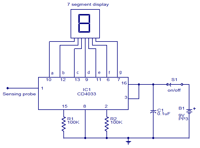
This circuit is designed to test the presence of mains voltage without direct electrical contact with the mains line. The core component of this circuit is the CMOS IC CD4033, which features a five-stage decade Johnson counter and an...

The PGA202 offset voltage correction circuit is designed to correct both input and output offset voltages. There are four different gain settings for the PGA202, which result in slight variations in input offset voltage. A 50k potentiometer is used...
In this circuit, an LM339 quad voltage comparator is utilized to generate a time delay and control a high current output at low voltage. Approximately 5 amps of current can be sourced using a pair of fresh alkaline D...
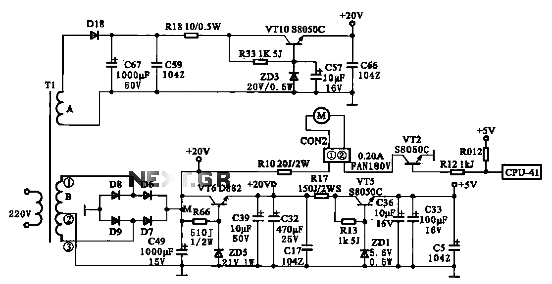
The JYC-22F type cooker low voltage power supply circuit is depicted. An AC 220 V power supply voltage is applied to a low-voltage transformer. The transformer has a primary winding (Tl) and two secondary windings (A and B), with...
When the push button is pressed, a clock pulse appears on the CLK input of flip-flop IC1b. The output then toggles, causing the LEDs to turn off. Simultaneously, IC1a is reset, silencing the buzzer. Pressing the button again will...

This is a small circuit designed for use as a charging controller or voltage limiter. It is particularly useful for creating a solar charger. The assembly of the circuit allows for modifications according to personal preferences. The circuit is...