
FAHRENHEIT CENTIG RADE LED THERMOMETER
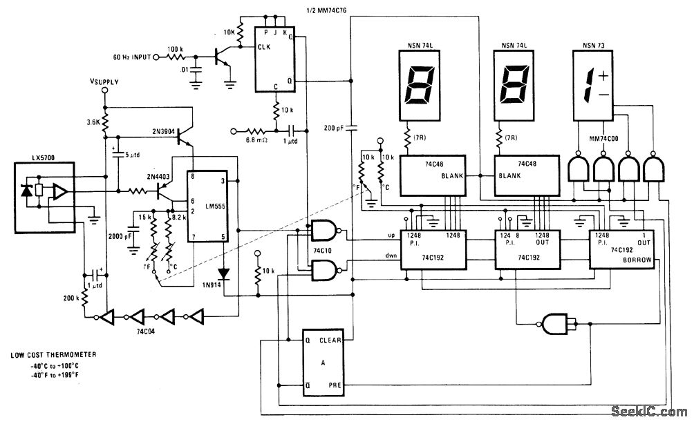
The National LX5700 is a precision temperature transducer designed to convert temperature variations into corresponding electrical signals. The device operates within a specified temperature range, making it suitable for various applications where temperature monitoring is essential.
The code conversion circuit associated with the LX5700 processes the output signals from the transducer, converting them into a digital format suitable for display. The circuit typically includes an analog-to-digital converter (ADC) that interprets the voltage output from the LX5700 and translates it into a binary code. This binary code is then utilized to control a 3-digit LED display, which visually represents the measured temperature.
The temperature range of the device extends from -40°F to +100°F or from -40°F to +199°F, allowing for flexibility in applications where different temperature thresholds are relevant. The ganged switch serves as a control mechanism, enabling users to select the desired temperature range for display. This feature enhances the usability of the temperature measurement system, allowing for quick adjustments based on the specific needs of the user.
In summary, the integration of the National LX5700 temperature transducer with a code conversion circuit and a 3-digit LED display provides an efficient and effective means for monitoring temperature across a broad range, facilitating precise temperature readings in various electronic applications.National LX5700 temperature transducer provides input for code conversion circuit driving 3-digit LED display indicating temperature range from -40ƒ to +100ƒ or -40 °F to +199 °F under control of ganged switch. -"Linear Applications , Vol. 2, " National Semiconductor, Santa Clara CA. 1976, LB-30. 🔗 External reference
Related Circuits
This circuit can switch two or more devices on and off in response to a series of rapid handclaps. The claps are picked up by an electret microphone. The circuit operates by utilizing an electret microphone, which serves as the...
The circuit employs 60 individual LEDs to represent the minutes of a clock and 12 LEDs to indicate the hours. The power supply and time base circuitry are consistent with those described in the previous 28 LED clock circuit....
How many different conditions can be indicated with just one LED? Two, perhaps three? Using this simple circuit, many more can be signaled! This circuit employs a two-color LED, which consists of two light-emitting chips, typically red and green,...
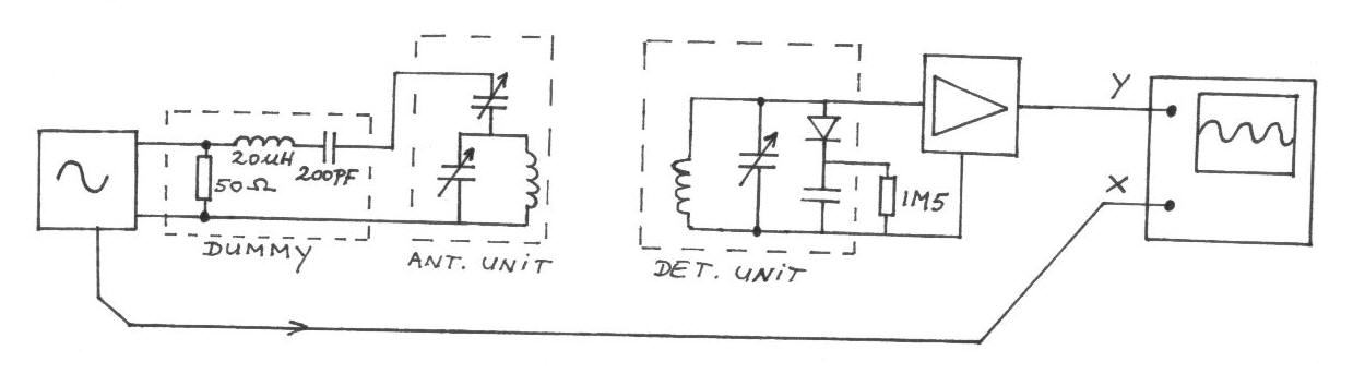
The frequency remains constant, oscillating between two predetermined values. On the oscilloscope display, a frequency spectrum is observed, showcasing the response curves of the two circuits. The input voltage of the receiver is 0.1 Volt peak-to-peak, while the voltage...
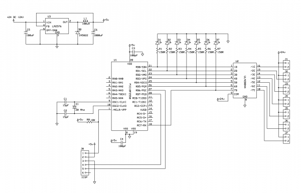
This project demonstrates the construction of a simple LED light string display utilizing seven 24V LED light strings. The project was designed for Christmas 2009 to adorn a balcony with lights. The light strings are widely available, particularly in...

This voltage booster circuit for driving one or more white LEDs utilizes a 555 timer as its main component. The timer, designated as IC1, operates as a resettable astable multivibrator with R1, R2, and C2 serving as the timing...
Warning: include(partials/cookie-banner.php): Failed to open stream: Permission denied in /var/www/html/nextgr/view-circuit.php on line 713
Warning: include(): Failed opening 'partials/cookie-banner.php' for inclusion (include_path='.:/usr/share/php') in /var/www/html/nextgr/view-circuit.php on line 713