
1.5 W linear Power Amplifier

Input (red) Output (blue) Driver (black)
Let's start focusing on the output stages. At RF out you find a 50 ohm resistor which represent an antenna. The DC voltage is 12V which also will be the peak voltage of a sine signal. Let's say we want our transmitter to deliver 5W. We can then use the formula to calculate the necessary impedance. R = U2/2P = 12*12/2*5 = 14.4 ohm.
The driver (transistor) want to see a 14.4 ohm load to be able to deliver 5W of power. As you can see the antenna is 50 ohm and we wish to have 14.4 ohm load, so we must have some kind of impedance transformation. A commonly used impedance transformer is the pi-filter. It consist of 2 capacitors and an inductor. At the input stage we will have the opposite relation. The driver (transistor) has a low impedance (1-10 ohm) and we wants the input to be 50 ohm which is a kind of standard. An important note is that the transistor has a stray capacitance Cce from emitter to collector. You can find this data in the datasheet of the RF transistor. As you can see, Cce is parallel with C3. When you have calculated C3, you must subtract the stray capacitance Cce to get correct value of C3. Below I explain how to calculate pi-filters.
L2 is a large inductor which is not critical in value (1-100uH). Sometimes a ferrite pearl will do the job. L2 act as high impedance (invisible) for RF signal, but it will give the base of the transistor a DC voltage grounding.
Again we need a transforming stage to convert the input power with 50 ohm impedance to (1-10 ohm) impedance at the driver input. Most often the input impedance of the driver is not purely resistive, it also contain a reactive part. In this example the input impedance is (5-j5) ohm.
The project involves the design and construction of a 1.5W power amplifier (PA) transmitter, focusing on the principles of signal processing and impedance matching. The transmitter will utilize a class-C amplifier configuration, which is known for its efficiency in RF applications. The circuit consists of three main stages: the input stage, the driver stage, and the output stage.
The input stage is designed to accept a 50-ohm signal, typical for RF applications. The driver stage, which utilizes a transistor, requires a low impedance load of approximately 14.4 ohms to deliver the desired 5W output. This necessitates the use of an impedance transformer, typically implemented using a pi-filter configuration comprising two capacitors and an inductor. In this design, the stray capacitance (Cce) of the transistor must be accounted for when calculating the capacitance values in the pi-filter.
The output stage is connected to a 50-ohm antenna, which serves as the load for the transmitter. The DC supply voltage is set at 12V, which also corresponds to the peak voltage of the sine wave output. The design calculations reveal that a large inductor (L2) is employed to provide high impedance at RF frequencies while ensuring proper DC grounding for the transistor's base.
In summary, this transmitter design emphasizes the importance of impedance matching and the use of reactive components to optimize performance, thereby enabling efficient power delivery to the antenna while maintaining signal integrity.I will also explain how you can build a 1.5W PA transmitter. The project will include PCB, components and instructions how to make coils, assembly and testing. First let's discuss and learn about the RMS value of a sine signal. Take a look at the picture at right. The left figure shows a square wave signal (blue) and to the right you see a sine wave signal (red). The coloured area show the time integration of the DC voltage. The area will later on represent the power your will get from the specific signal shape. The relationship between the two shapes are 1 to 1/rot(2). It gives about 1 to 0.707. This means that if you put 1 W power from a square wave or pure DC signal into a load, you will only get 0.707 W from a sine wave signal with equal amplitude. From the figures you will easy see that the area of the sine wave is less than the area of the square wave.
You can also think like this: Let's say you want to heat up a resistor with the two signals. To achieve equal amount of power (heat) in the resistor, the sine wave must be rot(2) times larger in amplitude than the square wave or constant DC signal. It is time to look at the class-C amplifier and try to identify the different stages. You will find 3 stages. Input (red) Output (blue) Driver (black) Let's start focusing on the output stages. At RF out you find a 50 ohm resistor which represent an antenna. The DC voltage is 12V which also will be the peak voltage of a sine signal. Let's say we want our transmitter to deliver 5W. We can then use the formula to calculate the necessary impedance. R = U2/2P = 12*12/2*5 = 14.4 ohm. The driver (transistor) want to see a 14.4 ohm load to be able to deliver 5W of power. As you can see the antenna is 50 ohm and we wish to have 14.4 ohm load, so we must have some kind of impedance transformation.
A commonly used impedance transformer is the pi-filter. It consist of 2 capacitors and an inductor. At the input stage we will have the opposite relation. The driver (transistor) has a low impedance (1-10 ohm) and we wants the input to be 50 ohm which is a kind of standard. An important note is that the transistor has a stray capacitance Cce from emitter to collector. You can find this data in the datasheet of the RF transistor. As you can see, Cce is parallel with C3. When you have calculated C3, you must subtract the stray capacitance Cce to get correct value of C3. Below I explain how to calculate pi-filters. L2 is a large inductor which is not critical in value (1-100uH). Sometimes a ferrite pearl will do the job. L2 act as high impedance (invisible) for RF signal, but it will give the base of the transistor a DC voltage grounding.
Again we need a transforming stage to convert the input power with 50 ohm impedance to (1-10 ohm) impedance at the driver input. Most often the input impedance of the driver is not purely resistive, it also contain a reactive part.
In this example the input impedance is (5-j5) ohm. 🔗 External reference
Related Circuits
This article discusses several opamp-based headphone amplifier circuits, including suggestions for selecting opamps, input coupling and filtering, high current output stages and power supply options. There are no recommendations for specific opamp brands or models. For tube devotees, there...
Construct a basic audio amplifier utilizing transistors. While integrated circuit (IC) designs are available for this purpose, the intention is to use transistors to gain practical knowledge about their amplification capabilities. The article "Amplifier Basics - How Amps Work...
This is a schematic diagram of a general-purpose audio frequency (AF) amplifier circuit. The circuit employs inexpensive 1/4-W resistors, as high precision is not required. The general-purpose audio frequency (AF) amplifier circuit is designed to amplify audio signals for various...
The LM231 and LM331 family of voltage-to-frequency converters are well-suited for use in simple, low-cost circuits designed for analog-to-digital conversion, precision frequency-to-voltage conversion, long-term integration, linear frequency modulation or demodulation, and various other applications. When utilized as a voltage-to-frequency...
That RF Amplifier is for boosting small fm transmitters and bugs. It uses two Philips 2N4427 and its power is about 1 Watt. At the output, you can drive any linear with BGY133 or BLY87 and so on. Its...
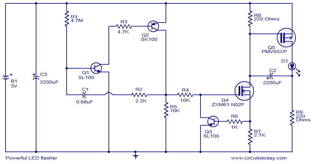
This circuit diagram illustrates a powerful LED flasher utilizing a 1W high power LED, which is widely available in the market. Transistors Q1 and Q2 are configured as an oscillator that generates positive pulses with a duration of 20...