
Bench top power supply
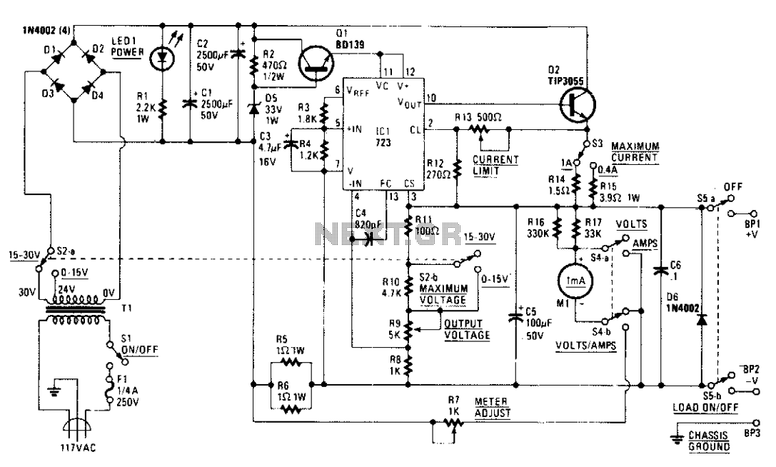
The circuit begins with a tapped transformer that provides multiple voltage outputs based on the selected tap via switch S2a. The diode bridge rectifies the AC voltage produced by the transformer into a pulsating DC voltage. The two 2500 µF filter capacitors (C1 and C2) smooth out the rectified output, yielding a stable DC voltage of either 37 volts or 47 volts, depending on the transformer tap selected.
The unregulated DC voltage is then directed to a pre-regulator stage composed of a transistor (Q1) and a Zener diode (D5). This stage is crucial for protecting the voltage regulator IC (IC1, the 723) from voltage levels exceeding its maximum rating of 40 volts. The Zener diode clamps the voltage to a safe level, ensuring that IC1 operates within its specified limits.
An LED (LED1) connected with a 2.2 kΩ current-limiting resistor (R1) serves as a power indicator, illuminating when the circuit is powered. The LED's brightness may vary slightly with different transformer taps, but this variation does not significantly impact the overall functionality of the circuit.
The 723 voltage regulator IC is designed to maintain a constant output voltage by adjusting the pass transistor (Q2) in response to load changes. Q2, configured as a voltage follower, provides current amplification, allowing the circuit to deliver sufficient current to the load. With a maximum collector current rating of 15 amps and a maximum VCE of 70 volts, Q2 is well-suited for this application, ensuring reliable performance under varying load conditions. This design effectively combines voltage regulation and power handling capabilities, making it suitable for various electronic applications.A tapped transformer drives a diode bridge (D1-D4) and two 2500 µ¥ filter capacitors (Cl and C2), that provide a no-load voltage of 37 or 47 volts, depending upon the position of switch S2a. The unregulated dc is then fed to a pre-regulator stage composed of Ql and D5. Those components protect IC1 (the 723) from an over-voltage condition; the 723 can't handle more than 40 volts.
The LED (LED1) and its 2.2 k current-limiting resistor (Rl) provide on/off indication. The current through the LED varies slightly according to the transformer tap selected, but that's of no real consequence. The series-pass transistor in IC1 drives voltage-follower Q2, providing current amplification. The transistor can handle lots of power. It has a maximum collector current of 15 amps and a maximum VCE of 70 V, both of which are more than adequate for our supply. 🔗 External reference
Related Circuits

This is a 1-amp variable-voltage power supply unit (PSU) that can adjust output voltage from approximately 3V to 24V. It features a maximum output current limit, which is particularly useful when powering up a project for the first time...
This circuit generates a constant current, constant voltage switched-mode power supply (SMPS). It is designed to efficiently charge a battery using a constant current, constant voltage approach. The circuit operates as a constant current, constant voltage SMPS, which is crucial...
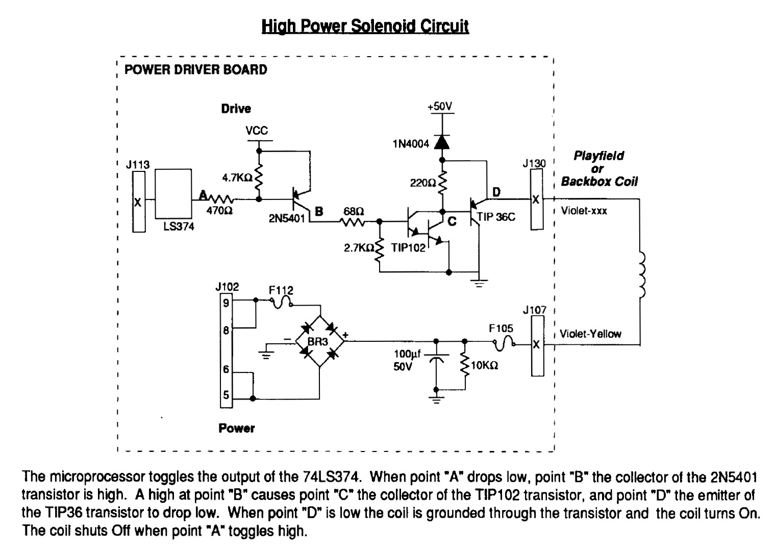
Instructions for using an LED-Wiz to control pinball solenoids. Rottendog Amusements manufactures modern replacement driver boards, such as the Williams WPC89/WPC-S replacement. Although this board is an improvement over the originals, it remains relatively large and is capable of...
The supply receives -20 V from the rectifier/filter which is fed to the collector of the Darlington pnp pass transistor, a TIP105. The base drive to the TIP105 is supplied through resistor R5. The base of the TIP is...
To celebrate the hundredth design posted to this website and to fulfill the requests of many correspondents wanting an amplifier more powerful than the 25W MosFet, a 60 - 90W high-quality power amplifier design is presented here. The circuit...
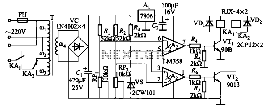
It utilizes two LM358 operational amplifiers, A2 and Ar, to create a voltage measurement comparison control circuit for upper and lower limit voltage settings. The circuit includes a Raspberry Pi adjustment potentiometer (RPi) and an additional potentiometer (RP2) to...