
power supply How to measure the capabilities of a wall adapter
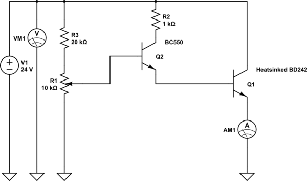
The device in question operates as a passive power injector, which utilizes its pins to provide a nominal voltage of 24V under no load conditions. The specified pins, +4, 5 and -7, 8, indicate the power output and ground reference points, respectively. The passive nature of the injector implies that it does not actively regulate the voltage under load, which can lead to voltage drop issues when a significant current draw is applied.
When a load of 1A was introduced, the device's protective circuitry engaged, resulting in the voltage dropping to 0V. This behavior is indicative of an overcurrent protection feature designed to safeguard the device from potential damage due to excessive current draw. Such protections are critical in ensuring the longevity and reliability of electronic components.
The suggestion made by user2020 to dissipate excess power into a transistor's heatsink is a practical approach to managing thermal load. By redirecting the power that would otherwise cause voltage drops or potential damage, the heatsink can absorb and dissipate heat, thus maintaining operational stability. This method requires careful consideration of the transistor's thermal characteristics and the overall circuit design to ensure that the heatsink can effectively manage the thermal load without compromising the performance of the device.
In summary, the device's operation as a passive power injector, combined with its protective features and potential for thermal management through a transistor heatsink, highlights the importance of circuit design and component selection in achieving reliable electrical performance. Further exploration into the implications of these design choices can lead to improved efficiency and enhanced device functionality.The device exhibits 24V at no load on pins +4, 5 and -7, 8. According to Wikipedia, this is called a passive power injector. I tried drawing 1A from the device and failed (some protection drops the voltage to 0V). @W5VO, thank you for your care of the question. However, protecting it removed the answer of a new user, user2020 I believe, that contai ned the interesting idea of dumping the power into the heatsink of a transistor. How do we bring it back (or you think it is a bad answer ) Vorac Mar 11 `13 at 12:30 🔗 External reference
Related Circuits
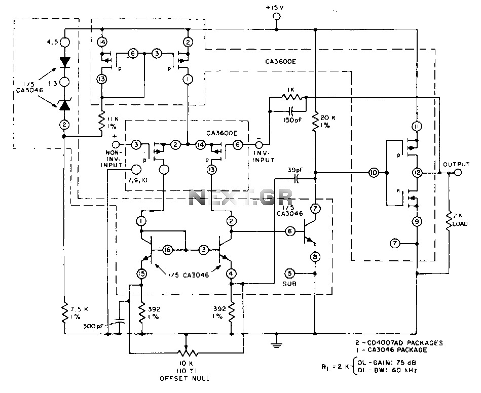
This unity-gain follower amplifier features a CMOS p-channel input, an NPN second-gain stage, and a CMOS inverter output. The integrated circuit components consist of two CA3600E CMOS transistor pairs and a CA3046 NPN transistor array. A zener-regulated leg provides...
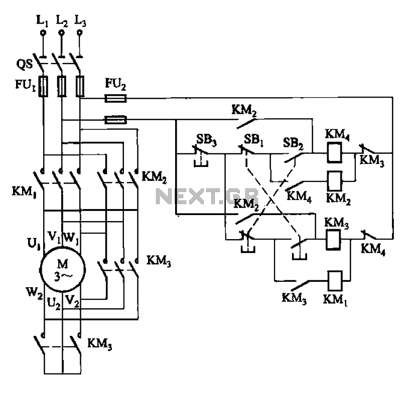
33 kW and above windlass with Y-conversion power-saving circuit The circuit design for a windlass rated at 33 kW and above incorporates a Y-conversion power-saving mechanism. This design is crucial for optimizing the efficiency of the windlass, which is commonly...
Here is something that may interest crystal radio builders: a one-transistor (silicon) AM broadcast receiver that derives its power from ambient AC hum and static. The schematic is adapted from Darryl Boyd's "Stay Tuned" website, which features over 170...
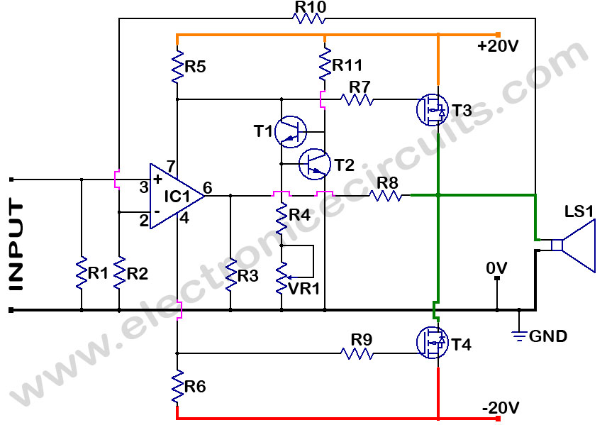
MOSFET Power Amplifier Circuit diagrams. Two complementary MOSFETs are used to deliver 20W into 8Ω. The described MOSFET power amplifier circuit utilizes two complementary MOSFETs, which are arranged in a push-pull configuration to efficiently amplify audio signals. The circuit is...
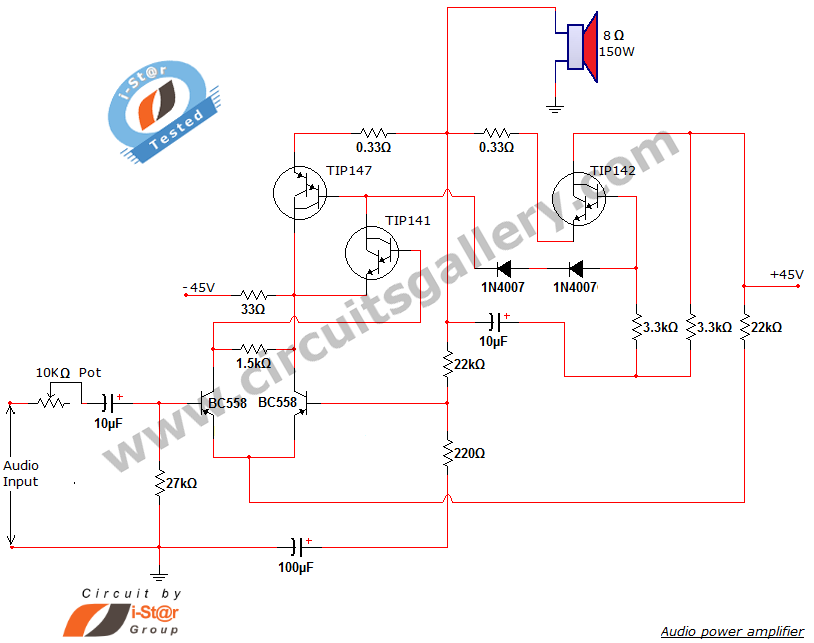
This document presents a new audio power amplifier schematic utilizing TIP darlington pair transistors. It is suitable for both home audio and car audio amplifiers. The TIP142 and TIP147 darlington pair transistors create a push-pull high-power amplifier configuration, while...
The objective is to enhance information transmission through the distribution of articles. Please contact us via email at [email protected] within 15 days if there are any issues related to article content, copyright, or other concerns. Prompt action will be...
Warning: include(partials/cookie-banner.php): Failed to open stream: Permission denied in /var/www/html/nextgr/view-circuit.php on line 713
Warning: include(): Failed opening 'partials/cookie-banner.php' for inclusion (include_path='.:/usr/share/php') in /var/www/html/nextgr/view-circuit.php on line 713