
Clock-Driven Triangle-Wave Generator Circuit
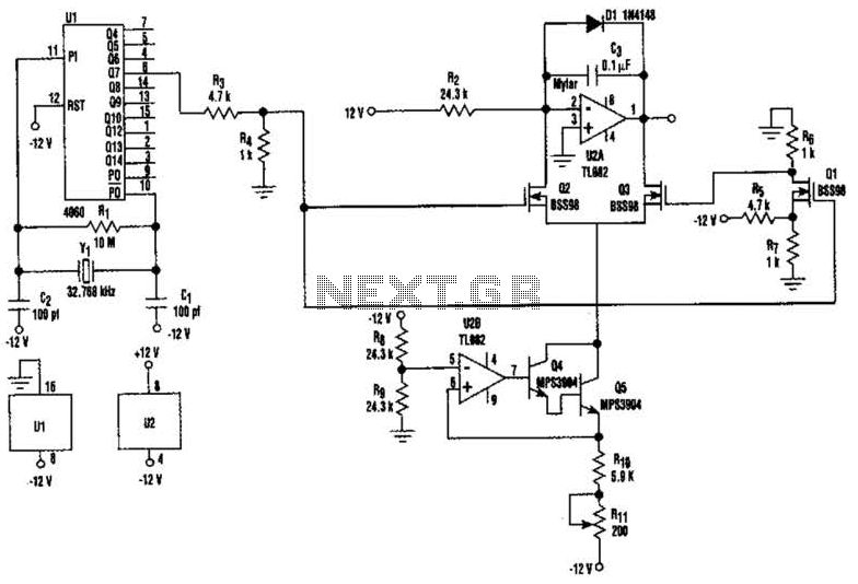
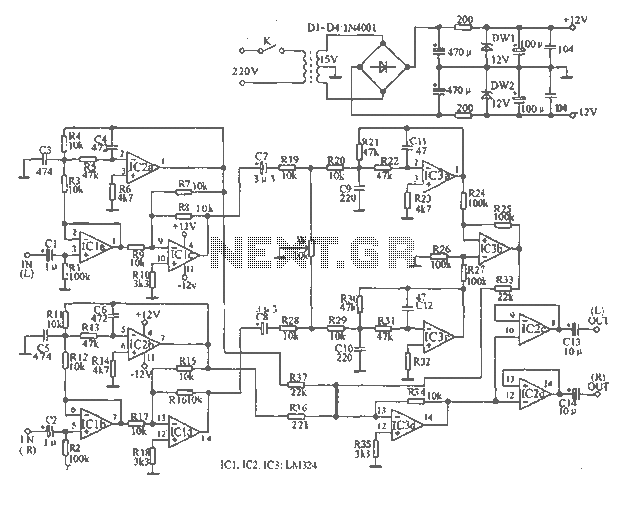
The circuit described involves a combination of operational amplifiers and transistors to achieve specific signal processing functions. The integrator circuit comprising U2-a, U3, and R2 is designed to integrate the input signal over time, producing a voltage output that is proportional to the area under the input waveform. This is particularly useful in applications where the accumulated value of a signal is required, such as in analog computing or signal conditioning.
Transistors Q2 and Q3 are utilized as switches that alternate at a frequency of 256 cycles. This switching action is critical for controlling the operation of the integrator, allowing it to reset periodically or change its operational state, thereby influencing the output waveform characteristics.
The second part of the circuit involves U2-b, Q4, Q5, and resistors R8 through R11, which collectively act as a constant current generator. This configuration is essential for maintaining a steady current flow regardless of load variations, ensuring that the subsequent stages of the circuit operate reliably. Resistor R11 is specifically calibrated to produce a symmetrical triangular waveform, which is a common requirement in waveform generation applications. The triangular waveform is characterized by its linear rise and fall times, making it suitable for various applications, including modulation and signal processing.
Overall, this circuit exemplifies an integrated approach to signal processing, combining integration and waveform generation in a cohesive design. The careful selection of components and their configuration enables precise control over the output characteristics, making it applicable in a wide range of electronic applications. U2-a, 03 and R2 operate as an integrator. Q2 and Q3 are alternately switched at 256 cycles. U2-b, Q4, Q5, and R8 through Rll arc a constant current generator, and Rll is set for a symmetrical triangular waveform. 🔗 External reference
Related Circuits
The main circuit of the 6-channel mixer consists of six input channels. Channels 1-4 are mono, while channels 5-6 are designed for music use. The number of input channels can be increased as desired. The output of each channel...
The integrated circuit LA3607 enables the configuration of a 7-band graphic equalizer for a single audio channel by incorporating additional capacitors and variable resistors. The cutoff frequency can be modified using variable resistors. It demonstrates high stability when handling...
The circuit employs a widely used Sharp IR module (the Vishay module may also be utilized). The pin numbers indicated in the circuit pertain to both the Sharp and Vishay modules. For other modules, it is recommended to consult...
The tape output circuit processes the left and right channel signals through a first buffer amplifier. The output signal is split into two paths: one route directly connects to an amplifier for amplification, while the other route passes through...
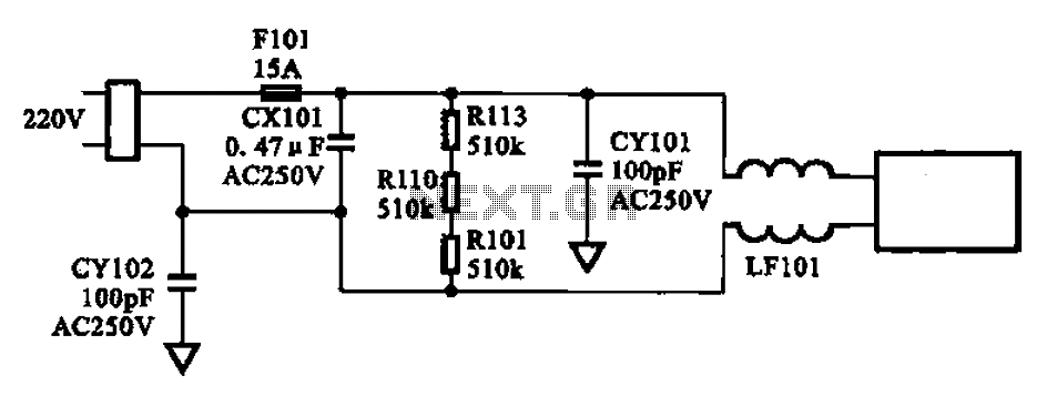
The AC input circuit consists of a fuse (Fl01), a mutual inductance filter (LF101), and filter capacitors (CX101, CY101, CY102), among other components. Its primary function is to filter out noise and pulse interference from the AC circuit, as...
Most operational amplifier circuits require a dual-polarity power supply - one having +V and -V. However, there are times when a DP supply simply isn't conveniently available. Single-polarity modifications to DP designs often achieve their effect by referencing the...
Warning: include(partials/cookie-banner.php): Failed to open stream: Permission denied in /var/www/html/nextgr/view-circuit.php on line 713
Warning: include(): Failed opening 'partials/cookie-banner.php' for inclusion (include_path='.:/usr/share/php') in /var/www/html/nextgr/view-circuit.php on line 713