
1 Transistor Audio Mixer

The described circuit functions as a basic audio signal mixer, allowing users to blend two distinct audio sources effectively. The primary inputs, designated as Input1 and Input2, serve different purposes: Input1 is intended for a dynamic microphone, which captures vocal audio, while Input2 is designed for instrumental music tracks that do not contain vocal elements.
The variable resistors (VR1 and VR2) act as volume controls for each input, enabling the user to adjust the amplitude of the audio signals independently before mixing. This feature is crucial for achieving a balanced output, as it allows the user to increase or decrease the volume of each source according to preference.
VR3 serves as a balance control, allowing for fine-tuning between the two inputs. By adjusting VR3, the user can emphasize one audio source over the other, facilitating a more tailored sound experience.
The output of the mixer combines the adjusted signals from Input1 and Input2, producing a mixed audio signal that can be sent to a speaker or other audio output device. An additional variable resistor, VR4, is included as an optional feature to control the overall output volume, providing further flexibility in managing the final audio level.
In summary, this classic signal mixer circuit is designed for straightforward audio mixing applications, making it suitable for various scenarios, such as live performances, home studios, or any setting where mixing vocal and instrumental audio is required.This is a classic signal mixer that is used for audio purpose. VR1 & VR2 are inputs audio volume controlers and VR3 is used to control the balance between Input1 and Input2. connect a dynamic microphone to Input1 and a music without vocal to Input2, then adjust the VR1, VR2 and VR3 for obtaining a good mixed audio signal from the circuit Output.
VR4 is an optional volume control for output audio signal. 🔗 External reference
Related Circuits
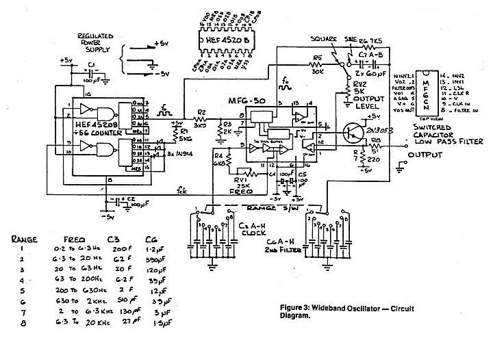
A low distortion audio frequency sine wave can be generated by passing the output of a simple square wave oscillator through a sharp cutoff low-pass filter to attenuate the odd harmonic components. The output level of the sine wave...
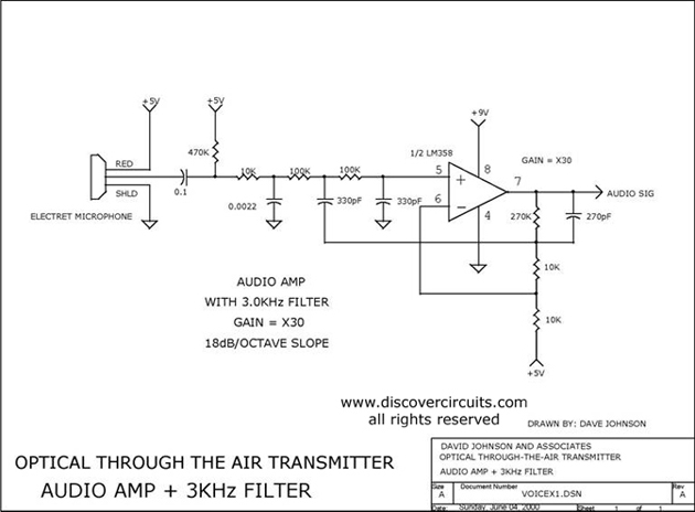
Audio amplifier with a 3 kHz filter. This circuit serves as the audio amplification section for a complete optical transmitter. It amplifies and filters voice audio signals from an electret microphone. The audio amplifier circuit is designed to enhance the...
The circuit presented is experimental and should provide some fun to build and play about with. It has been built and tested and works very well indeed. Please note that it is a low current Class-A opamp and is...
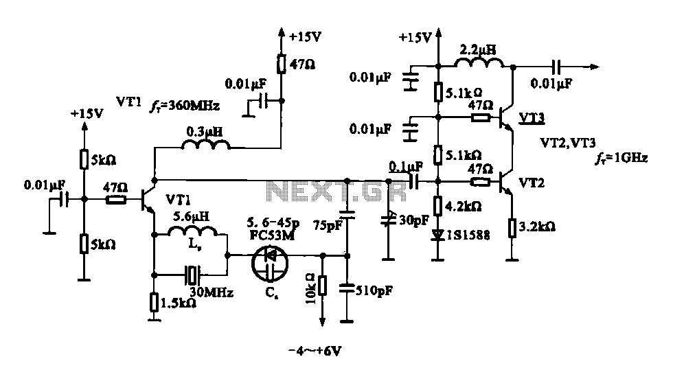
A variable frequency oscillator transistor circuit, primarily functioning as an oscillator, incorporates a crystal resonator and a varactor diode. The output is amplified, typically used for generating high-frequency signals. This 30 MHz transistor circuit features an inductor (LP) connected...
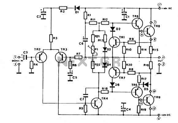
This amplifier features a high-quality circuit equipped with complete short circuit protection and exhibits very low total harmonic distortion (T.H.D.) across a full range of frequencies. It requires a symmetrical power supply of ±40V. The output power transistors are...
This single transistor audio mixer is utilized in an amplifier circuit design featuring a base-driven transistor, where the emitter is current-controlled. The majority of the driving current flows through the collector. This audio mixer circuit employs a single transistor to...