
10 Band Graphic Equalizer
The circuit for this device should be constructed in two separate pieces, each corresponding to a different channel. The regulation of these channels is controlled by a potentiometer, which should be a fader type. A switch, labeled as S1, is incorporated into the design to bypass the circuit. This allows the musical program to pass through unaltered, a state also known as FLAT. The gain of each channel can be adjusted using the potentiometer RV1.
Expanding on this, a graphic equalizer typically consists of a series of filters each centered on a specific frequency. By adjusting the level of these filters, users can control the frequency response of the system. The two separate pieces of the circuit correspond to the left and right channels of a stereo system, allowing for independent control over each channel's frequency response.
The fader type potentiometer is a device that allows for the smooth adjustment of the signal level in each channel. This can be used to balance the audio output or to create special effects by emphasizing or de-emphasizing certain frequencies.
The inclusion of a bypass switch is a practical feature, as it allows users to quickly compare the altered and unaltered audio signals. This can be useful for checking the effect of the equalizer settings and for ensuring that the audio signal is not overly distorted.
Finally, the potentiometer RV1 is used to control the overall gain of each channel. This allows for the adjustment of the output level of the equalizer, which can be used to match the input sensitivity of the following stage in the audio signal chain.With graphic equalizer we make selective cutting off or boost, of selected departments of acoustic spectrum. With this way we can adapt the musical reproduction, in the characteristics of space where we hear. This can create however also problems if go to far specifically in the gain of some area, with result the distortion.
The circuit should be made in two pieces, one for each channel, the potesometer regulation it should they are Fader. With switch S1 we can by pass the circuit, leaving the musical program, to pass without alteration (FLAT).
With the potesometer RV1 we regulate the gain of each channel. 🔗 External reference
Related Circuits
This wideband jammer simultaneously blocks all transmissions within a desired band by sweeping across the specified frequency range, starting from the lowest frequency to the highest. A linear sawtooth signal is applied to the modulator in the FM transmitter....
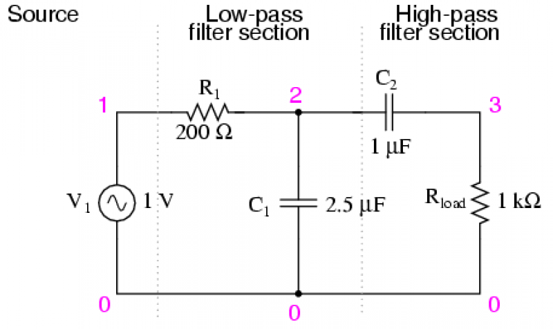
There are applications where a particular band, or spread, or frequencies need to be filtered from a wider range of mixed signals. Filter circuits can be designed to accomplish this task by combining the properties of low-pass and high-pass...
The antenna tuning circuit can accommodate 1/2 wave length antennas or higher, for input resistances of 50 Ohms which make it suitable for CB (Citizen Band) transceivers. C1 is for fine tuning and C2 is just for tuning. Turning...
A classic three-way tone control circuit that allows for the regulation of low, mid, and high frequencies of an acoustic signal. The boost/cut can be adjusted within a range of ± 18 dB/oct. The circuit operates on a supply...
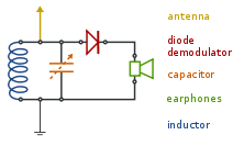
This is a crystal radio circuit that features a simple design but is ineffective in tuning to the medium wave AM broadcast band. Component: Antenna. The crystal radio circuit operates on the principle of radio wave detection using a crystal...
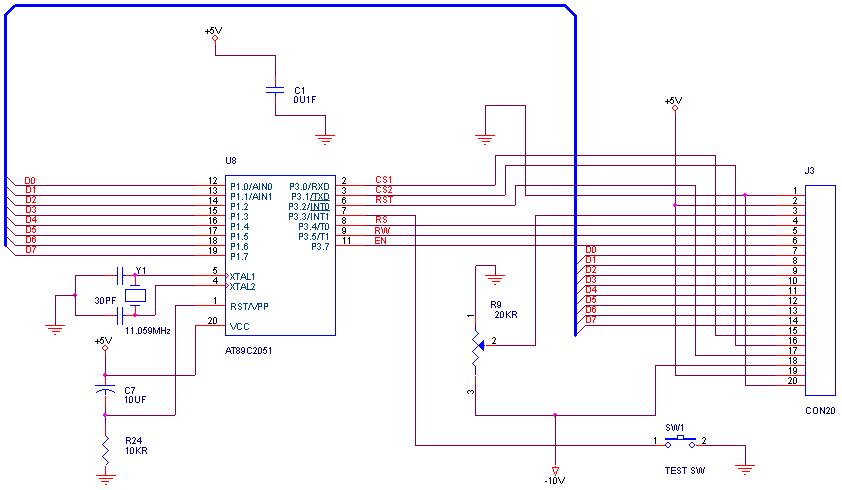
How can graphical LCDs be controlled using a microcontroller? Is there any datasheet available? Graphical LCDs (Liquid Crystal Displays) are widely used in various electronic applications for displaying complex graphics and text. To control these displays with a microcontroller, several...