
10 Band Graphic Equalizer
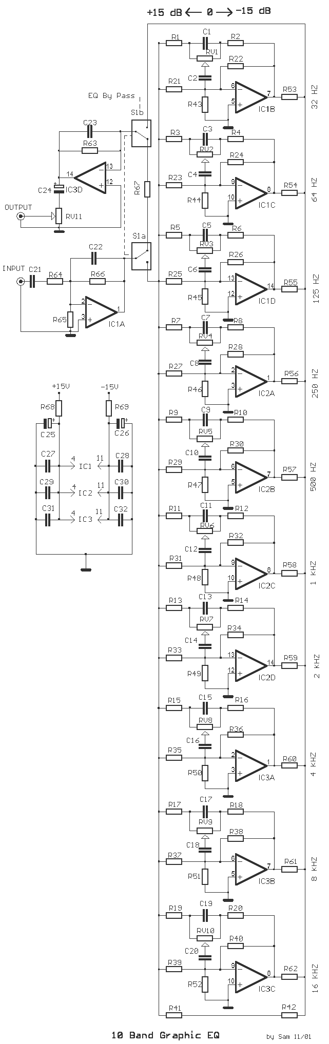
Each unit within this circuit shares common materials with the rest, with the only difference being the capacity of capacitors that form the filter in each unit. The position of the fader regulation runners, RV1 to RV10, determines the function of the unit. When the runner is centrally positioned, the filter does not intervene with the signal passing through it, and the gain of the particular unit is one [ X1 ].
However, if the runner is moved towards one side of the exit, the unit behaves as a cut-off filter for that specific range. This action results in the reduction or degradation of signals within the predetermined frequency range. Therefore, the circuit essentially functions as a frequency-specific amplifier or attenuator, depending on the position of the fader regulation runners.
The design and function of this graphic equalizer make it a flexible tool for modifying and customizing the output of audio signals. It allows the user to adjust the intensity of different frequency bands independently, thus providing a high degree of control over the sound profile. This is particularly useful in various audio applications such as music production, broadcasting, and sound reinforcement.The circuit of graphic equalizer, allocates ten adjusting potesometer , that each one from them affects in a predetermined area of frequencies, the central frequency of which abstains a octave (double), from the central frequencies of her neighbouring regions. Each unit has common materials with remainder and it differs only in the capacity of capacitors that constitutes the filter in each unit.
When the runner of fader regulation RV1 until RV10, is in the middle then we do not have no intervention of filter above in the signal that passes from in his and gain of particular unit, is one [ X1 ]. On the contrary if the runner is moved to a side of exit, the unit acts as filter of cutting off of area and it degrades the signals of predetermined area of frequencies.
🔗 External reference
Related Circuits
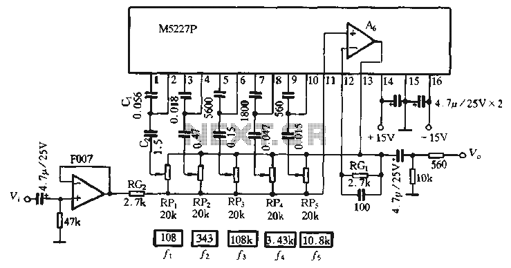
The M5227P is an application circuit designed for a graphic equalizer. Its control curve operates on a logarithmic frequency axis to represent the rate, requiring the same control curve pitch to ensure that all bands achieve maximum lift or...
How can graphical LCDs be controlled using a microcontroller? Is there any datasheet available? Graphical LCDs (Liquid Crystal Displays) are widely used in various electronic applications for displaying complex graphics and text. To control these displays with a microcontroller, several...
A circuit utilizing either the HA-2539 or HA-2540 in conjunction with two low-capacitance switching diodes can effectively separate signals exceeding 10 MHz. This configuration is particularly beneficial for applications such as full-wave rectification, AM detection, or synchronization generation. The described...
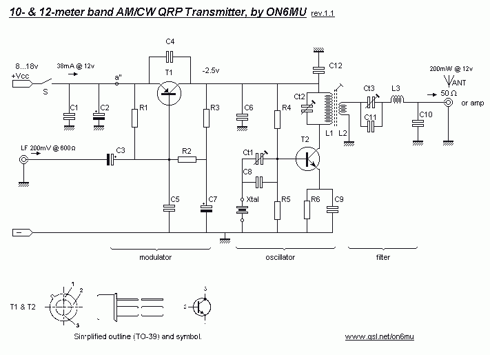
In this project, you will make a simple low-power broadcast-type circuit, using a crystal oscillator integrated circuit and a collector modulated AM oscillator. You can connect the circuit to an amplified microphone (no amplified microphone has a too low...
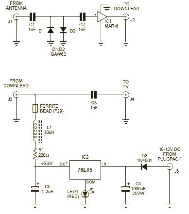
This wideband amplifier circuit is designed using the MAR-6 IC manufactured by Mini Circuits. The MAR-6 VHF-UHF wideband amplifier circuit provides a stable gain of at least 9 dB up to 2 GHz. Since the MAR-6 is designed to...
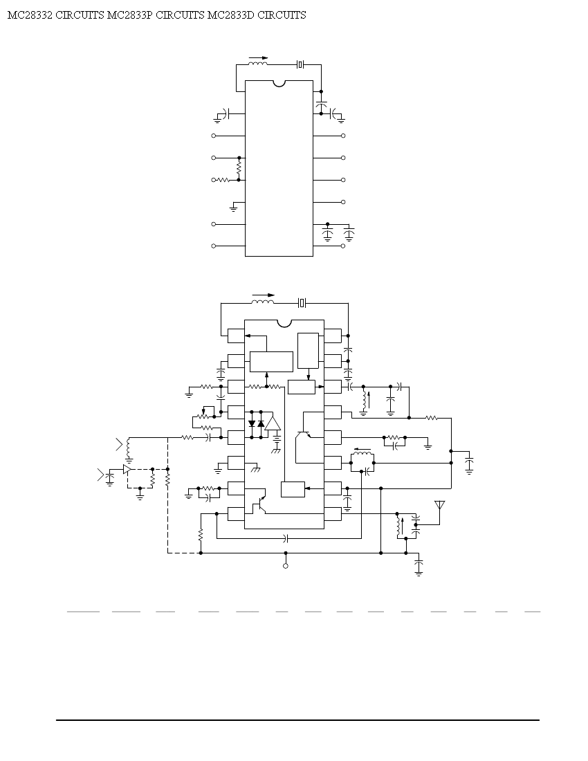
Crystal X1 operates in fundamental mode and is calibrated for parallel resonance with a load capacitance of 32 pF. The final output frequency is produced through frequency multiplication within the MC2833 integrated circuit (IC). The RF output buffer at...