
10-Band Graphic Equalizer

This audio equalizer circuit is designed to provide precise control over audio frequencies, allowing users to tailor sound output according to their preferences. The TL074 operational amplifier is selected for its low noise characteristics and high input impedance, making it suitable for audio applications. Each band-pass filter is configured to target specific frequency ranges, which can be adjusted via the associated potentiometers.
The circuit's architecture comprises 10 band-pass filters, each tuned to a different frequency range. The choice of capacitor values is critical; they are selected to define the cutoff frequencies of each filter, thereby allowing for effective equalization across the audio spectrum. The use of potentiometers enables real-time adjustments, facilitating fine-tuning of the audio output.
In stereo configurations, it is essential to ensure that both channels are matched in terms of component values and layout to maintain consistent audio quality. The isolation switch (S1) serves a dual purpose: it can disengage the equalizer from the audio path when not in use, preventing any unintended alterations to the audio signal, and it ensures a flat frequency response, which is crucial for accurate sound reproduction.
Power supply considerations are also vital; the circuit operates with dual power supplies, providing both positive and negative voltages. This configuration is necessary for the op-amps to function correctly, allowing them to amplify both the positive and negative halves of the audio waveform.
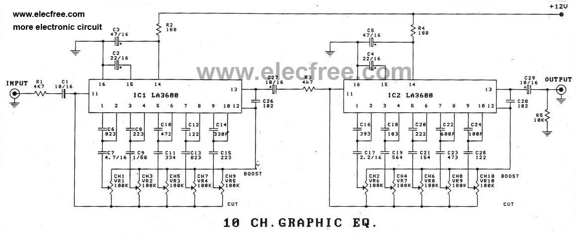
In summary, this audio equalizer circuit is a sophisticated tool for audio signal manipulation, designed with careful attention to component selection and circuit layout to achieve optimal performance in both mono and stereo applications. Proper implementation will enhance audio fidelity and allow for a customized listening experience.This circuit allows you to equlize the audio signals in 10 band. It uses low amount op-amps (TL074 - JFET op-amp) to anatomy a able blaster circuit. The affection of the architecture is a classical band-pass alive filter. The VCC is in ambit of 12 ~ 15 VDC and The VDD is in ambit of -12 ~ -15 VDC respectively. As shown in the diagram, there are 10 same units that only differ in capacitance values of capacitors which determine the frequency band of each filter. The potentiometers adjust the predetermined regions of frequency in each unit. If it is intended for stereo use then it will be supposed it is made in two pieces with as much as possible suited the materials, between the channels, so that do not exist differences in the regulation of each band frequencies.
Switch S1 isolates the circuit EQ, when him we did not need and it ensures level [ flat ] response in the exit of circuit. The circuit should be connected between preamplifier and in a final power amplifier. 🔗 External reference
Related Circuits
In addition to using the LA3600 IC, a 5-channel graphic equalizer can also be designed as a 10-channel graphic equalizer circuit through appropriate connections. The design of a 10-channel graphic equalizer circuit utilizing the LA3600 integrated circuit (IC) offers enhanced...
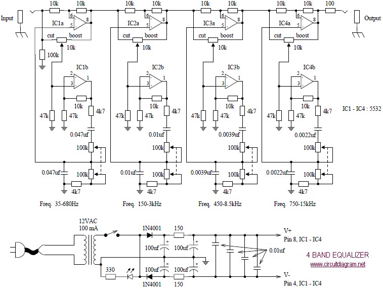
The following diagram illustrates a four-band blaster circuit. This blaster is utilized to enhance sound fidelity, emphasize specific instruments, eliminate unwanted noise, or create entirely new and distinct timbres. The four-band blaster circuit is designed to manipulate audio signals across...
This circuit is a five-channel equalizer designed for a single line channel. The working principle of this series involves a series of frequency filters with a center frequency of 10 Hz. The five-channel equalizer circuit is structured to manipulate audio...
The project described in this article is a constant Q, fully expandable graphic equaliser. Where most "conventional" graphic EQ circuits have a Q that is dependent on the setting of the pot, this one maintains the same Q at...
Another unit of graphic EQ with five bands. The basic difference with the other circuits is that instead of an IC, a transistor is used and the power supply goes up to +/- 24V DC, ensuring low distortion and...
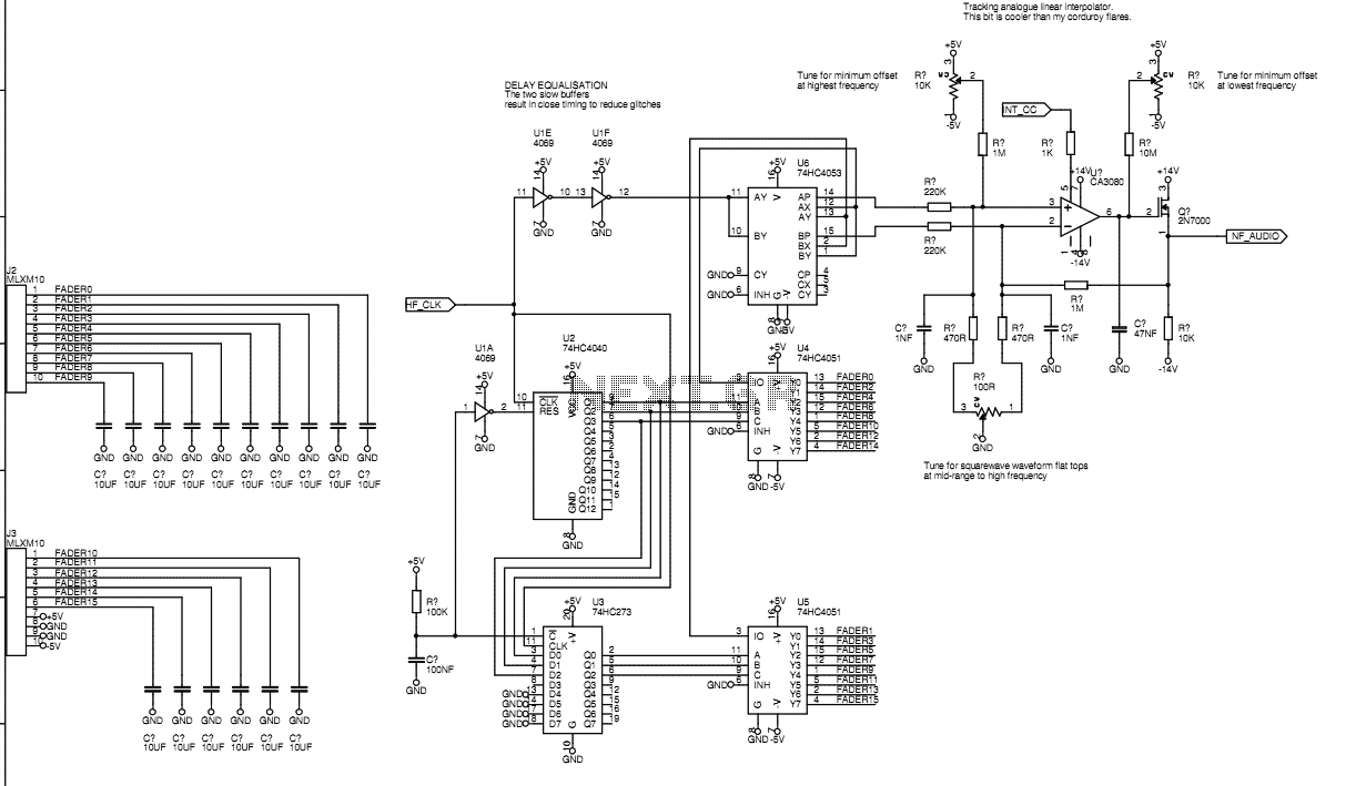
Originally I intended to have 32 faders. Once I tried fitting them on a veroboard, 32 seemed rather excessive so I have reduced to sixteen. This still allows generation of accurate eighth harmonic which compares well with the Hammond's...