
Simple 5 Band Equalizer Circuit
The five-channel equalizer circuit is structured to manipulate audio signals across different frequency bands, allowing for enhanced sound quality and customization of audio output. Each channel corresponds to a specific frequency range, enabling users to adjust the gain for bass, midrange, and treble frequencies effectively.
The circuit typically employs operational amplifiers (op-amps) configured as bandpass filters. Each filter is tuned to a specific center frequency, which in this case is set at 10 Hz. The use of a series of frequency filters allows for precise control over the audio signal, enabling the user to boost or cut specific frequency ranges according to their preferences.
In designing the equalizer, attention must be given to the selection of the appropriate resistor and capacitor values, which determine the cutoff frequencies and the Q factor of each filter. The gain of each channel can be adjusted using variable resistors (potentiometers), allowing for real-time manipulation of the audio signal.
Furthermore, the circuit can be powered by a dual power supply to ensure stable operation of the op-amps. It is also advisable to include bypass capacitors near the power supply pins of the op-amps to filter out any noise and ensure clean operation.
The output of the equalizer can be connected to an amplifier or directly to a speaker system, providing a versatile solution for audio applications. Proper grounding and shielding practices should be employed to minimize interference and ensure high-quality audio performance.This circuit is 5 channel Equalizer simply cheap (one line chanel). Working principle of this series is a series of frequentiefilter with center frequency of 10. 🔗 External reference
Related Circuits
This is a 3 Band Equalizer circuit designed to control the treble, midrange, and bass frequencies. The circuit utilizes a single operational amplifier (op-amp). The 3 Band Equalizer circuit serves to enhance audio signals by allowing users to adjust specific...
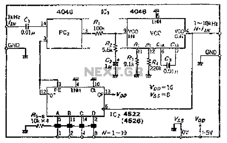
The CMOS IC 4046 Phase-Locked Loop (PLL) operates with a maximum frequency of 1 MHz. It is connected to a programmable divider, allowing it to process input frequencies. As the frequency increases by a factor of t, the circuit's...
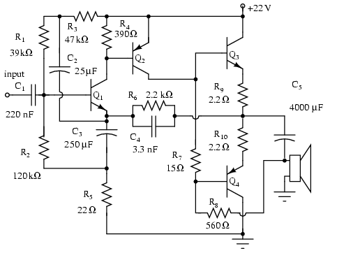
Note that Q3 and Q4 in the figure below are complementary, with Q3 being an NPN transistor and Q4 being a PNP transistor. This circuit is suitable for moderate power audio amplifiers. For a detailed explanation of this circuit,...
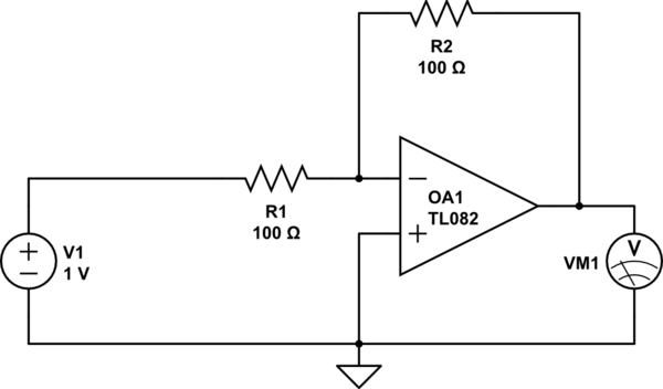
Considering a simple circuit as illustrated below, when the voltage source activates suddenly (changing from 0V to 1V), current will flow through the resistor R1. Assuming an ideal operational amplifier (op-amp) that draws no current, and an ideal voltmeter...
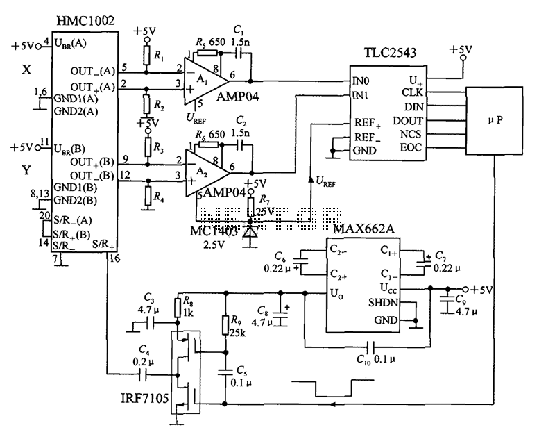
An application circuit for a biaxial magnetic field sensor is presented. This circuit utilizes the HMC1002 biaxial magnetic sensor along with two AMP04 amplifiers (A1, A2) to simultaneously measure magnetic fields in both the X-axis and Y-axis directions. The...
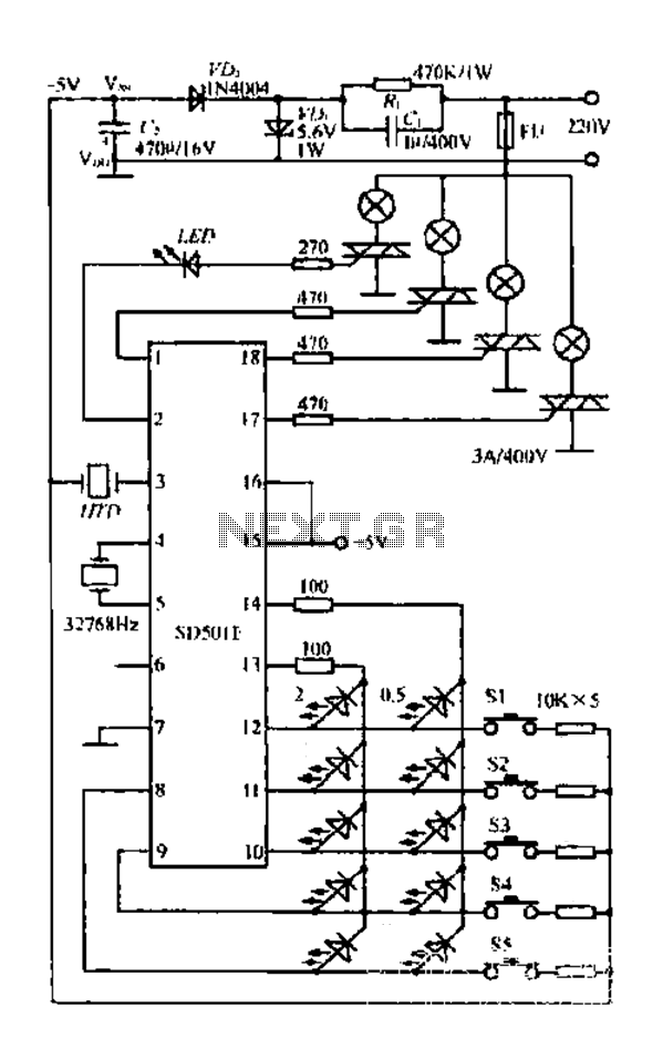
The FIG SD501E is a J tie fan integrated circuit (IC) characterized by progressive timing and three operational modes: strong, medium, and weak. It features three types of output settings and includes an electrical swing mechanism. The device is...