
10 band graphic equalizer

The graphic equalizer circuit is designed to allow users to manipulate audio signals across a range of frequencies, enhancing the listening experience by tailoring sound characteristics to personal preferences or environmental conditions. The ten potentiometers serve as controls for distinct frequency bands, typically including sub-bass, bass, low midrange, midrange, upper midrange, and treble frequencies, among others.
Each potentiometer is connected to a bandpass filter, which is configured to allow only the desired frequency range to pass through while attenuating frequencies outside this range. The spacing of one octave between the central frequencies ensures that each band operates independently without overlapping significantly with adjacent bands, allowing for precise adjustments.
The design of the equalizer employs standard electronic components, making it relatively easy to assemble and repair. The choice of capacitors in each filter design is critical, as it determines the cutoff frequencies and the bandwidth of each band. By selecting capacitors with varying capacitance values, each filter can be tailored to achieve the desired frequency response.
In practical applications, the graphic equalizer can be implemented in various audio equipment, including home audio systems, professional sound systems, and musical instruments. The ability to modify frequency response enhances the overall sound quality, making it a valuable tool for audio engineers and enthusiasts alike. The circuit's layout should ensure minimal signal interference and maintain signal integrity, which can be achieved through careful PCB design and component placement.The circuit of graphic equalizer, allocates ten adjusting potesometer , that each one from them affects in a predetermined area of frequencies, the central frequency of which abstains a octave (double), from the central frequencies of her neighbouring regions. Each unit has common materials with remainder and it differs only in the capacity of capacitors that constitutes the filter in each unit..
🔗 External reference
Related Circuits
This project utilizes the IRF510 MOSFET, a widely available N-Channel enhancement mode power field effect transistor. It is designed to withstand specified levels of energy in breakdown avalanche mode. Unlike bipolar transistors, which are current-controlled and have lower input...
The equaliser under discussion is specifically engineered to function as a preamp for musical instruments, notably the guitar, bass, and keyboard. This design sets it apart from the majority of conventional graphic equalisers, which typically offer a range from fully...
This complete high quality, low noise 5-BAND GRAPHIC EQUALIZER circuit is based around Monolithic Linear integrated circuit LA3600 manufactured by SANYO. This circuit is very easy to build and has good Quality. You can use it with Portable component...
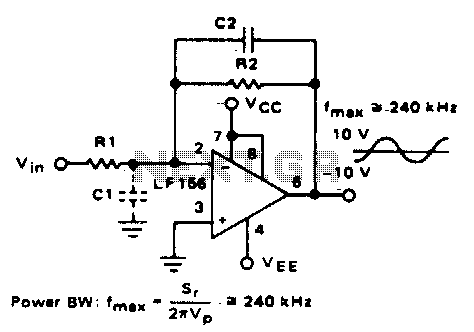
Parasitic input capacitance (ICi) is 3pF for LM5S, LF156, and LF157, along with any additional layout capacitance. This interacts with the feedback element and creates undesirable high-frequency effects. To mitigate this, a capacitor (C2) should be added in conjunction...

This circuit is a graphic equalizer that can be built with a low component count and is controlled using the LA3600 single IC chip. The internal design of the chip utilizes a transistor gyrator circuit, with connections to external...
This article provides a detailed overview of a 70 cm wideband transceiver designed for duplex operation. The modules operate within a 200 kHz wide duplex channel, selectable from 430-440 MHz with a 100 kHz channel spacing. Initial prototypes were...