
4 channel dimmer
The circuit design for the remotely controlled light dimmer integrates several key components to ensure functionality and reliability. The primary component is the TRIAC, which acts as a switch to control the power delivered to the lamp based on the phase control mechanism. The ramp generator circuit is crucial, as it produces the ramp signal that dictates when the TRIAC will be triggered. A capacitor is charged and discharged in a controlled manner to create the linear ramp voltage, which is then compared to the input control voltage.
The comparators play a vital role in determining the precise moment to trigger the TRIAC, enhancing the dimming capability by allowing for fine adjustments in brightness. The use of discrete transistors in the ramp generator not only simplifies the design but also provides robustness against variations in component characteristics.
The transformer selected for this application must meet specific criteria, including sufficient current rating and the inclusion of overload protection features. The design ensures that the circuit remains safe and functional under various load conditions. Additionally, the inclusion of adjustable trimmer R5 allows for calibration of the ramp signal, enabling users to fine-tune the dimmer's response to input signals.
Overall, this circuit exemplifies effective design principles in electronic dimming systems, combining simplicity with functionality while addressing safety and adaptability in real-world applications.Remotely controlled light dimmers in theatrical and architechtural applications use 0-10V control signal for controlling the lamp brightness. In this case 0V means that the lamp is on and 10V signal means that the lamp in fully on. A voltage between those values adjust the average voltage which is applied to the ligh bulb. This average voltage controlling is made by controlling the position in which phese the output triac fires (sooner it fires more power is applied to lamp). The the phase when the TRIAC will fire is controlled by the input voltage which is compared to an internal ramp signal generated by the dimmer.
In this arrangement the input voltage linearly controls the time delay between mains zero crossing and the triac triggering. This circuit is a real core of the dimmer system. This circuit generates ramp 100 Hz signal which is syncronized to the incoming mains voltage. The ramp signal which is generated will start form 10V and go linearly down to 0V in 10 milliseconds.
At the next mains voltage zero crossing the ramp signal will again immediatly start from 10V and go down to 0V. This same ramp signal is fed to all of the 4 comparators in the dimmer. The following ramp signal generator is quite simple ramp generator based on discrete transistors which do some switching, capacitor and a constant current source made by using one transistor.
The idea of the circuit is taken from N-channel light dimmer design made by Kari Hautio. Trimmer R5 is used in controlling the ramp signal. If you have an oscilloscope, then it is best to use it to look at the situation so that the signal send by the circuit is what is described eariler. A good approximation is so start at position that R5 is set to it`s center position. Besides generating the ramp signal the sampl generator circuit works as a power supply comaprator part of the dimmer.
The 13. 5V unstabilized output is used to power the comparator section (that putput can be loaded up to 100 mA). The 10V stabilized voltage is used only for internal use in ramp generator (that stabilized 10V voltage can be also used for some extra low power circuitry which need 10V voltage, for example local dimmer controls if such thign are needed).
The ramp generator used a normal mains transformer which can output at least 200 mA of current, because it powers both ramp generator itself and the voltage comparator circuits. I relected a tranformer which has an invernal overload protection inside the transformer (overhating protection fuse), so I did not need to add any extra fuses for this transformer.
If you use other kind of transformer, select a suitable fuse to protect it. In any case a 200 mA fuse on the secondary would be a good idea, propably also a primary fuse. R 🔗 External reference
Related Circuits
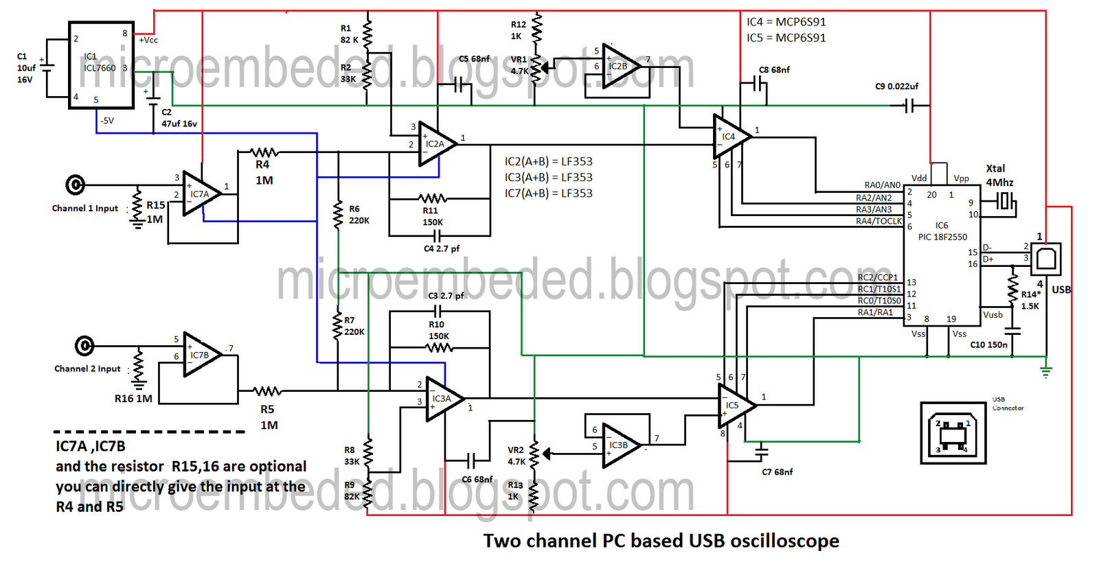
Portable PCs are now common, and a USB connection is a more effective solution. This document presents an oscilloscope that utilizes the USB port of a PC, operating at frequencies up to 10 kHz with an input voltage range...
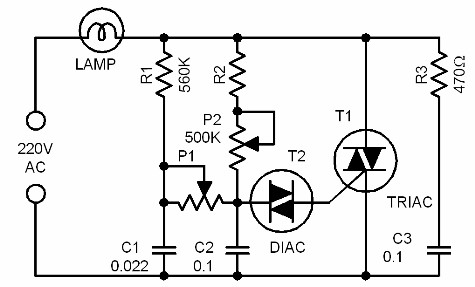
This is an advanced dimmer circuit design that allows the triac to be triggered at lower voltage levels. Typically, the triggering voltage for a triac is approximately 70V; however, this circuit enables triggering at around 35V through the incorporation...

A very simple dimmer circuit with only the essentials. In this circuit, the values are given for a BT138 at 220V AC. For 115V AC, experimentation with values may be necessary. R1 can vary from one triac to another;...
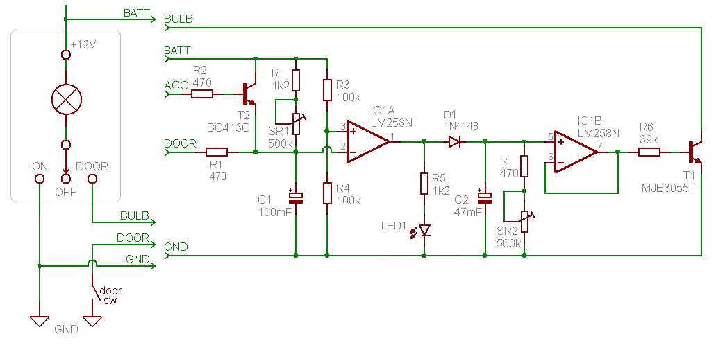
Introduction and disclaimer for individuals interested in a fading dome light (also referred to as courtesy light or theatre lighting) without incurring high costs. A fading dome light circuit is designed to create a gradual illumination effect, enhancing the aesthetic...
High-end audio equipment is typically controlled digitally by a microprocessor (microcontroller) system. It is necessary to have a digital interface that allows for effective communication and control. High-end audio systems utilize a microcontroller to manage various functionalities, enabling precise control...
Dimmer Switch - Dimmer Switch Working, Installation, Circuits and Explanation. A dimmer switch is a device that allows for the adjustment of the brightness of a light fixture. It operates by varying the voltage and current supplied to the light...