
Simple continuity tester

The PCB tracing tester operates by measuring the resistance across various points in a circuit. It distinguishes between short circuits and open circuits based on the resistance values encountered. When the resistance is below 50 ohms, the tester identifies this condition as a short circuit, indicating an unintended connection between conductive paths. Conversely, resistance values exceeding 100 ohms signal an open circuit, suggesting a break in the connectivity.
The core of the tester's functionality lies in its multivibrator circuit, which is triggered by the transistor T3. The base of T3 is connected to several components, including a diode (D1) and resistors (R1 and R2), which work together to control the switching behavior of T3. When the resistance at the test points is low, the multivibrator oscillates, providing an output that can be interpreted as a signal indicating a short circuit. In the absence of sufficient voltage, such as from a 1.5-volt supply, the tester may not be able to turn on any connected semiconductor devices, which limits its functionality in certain scenarios.
To enhance the performance of the tester, a higher voltage supply may be employed to ensure that the semiconductor components can be adequately activated. This adjustment would allow for more effective testing of components and circuits, improving the reliability of the results obtained during PCB diagnostics. The simplicity of the circuit design allows for easy troubleshooting and maintenance, making it an invaluable tool for electronics engineers and technicians when tracing wiring and diagnosing issues in printed circuit boards.This tester is for tracing wiring on Printed Circuit Boards. Resistors below 50 ohms act as a short circuit; above 100 ohms as an open circuit. The circuit is a simple multivibrator switched on by transistor T3. The components in the base of T3 are Dl, Rl, R2, and the test resistance. With a 1,5 volt supply, there is insufficient voltage to turn on a semiconductor connected to the test terminals.
Related Circuits

Generating sine waves with controlled frequencies over a wide range is challenging when using RC or LC sinusoidal oscillators. However, this can be effectively achieved using a wideband digital square wave oscillator, a counter, and a weighted summing network....
During rainy seasons, it can be quite bothersome when the car wipers operate continuously without pause. Have you ever considered implementing speed control for the wipers? While there are wiper control modules available commercially, many of them can be...

This compact tester checks cables for open-circuit or short-circuit conditions. A differential transistor pair at one end of each cable line remains balanced as long as the same clock pulse generated by timer IC appears at both ends of...
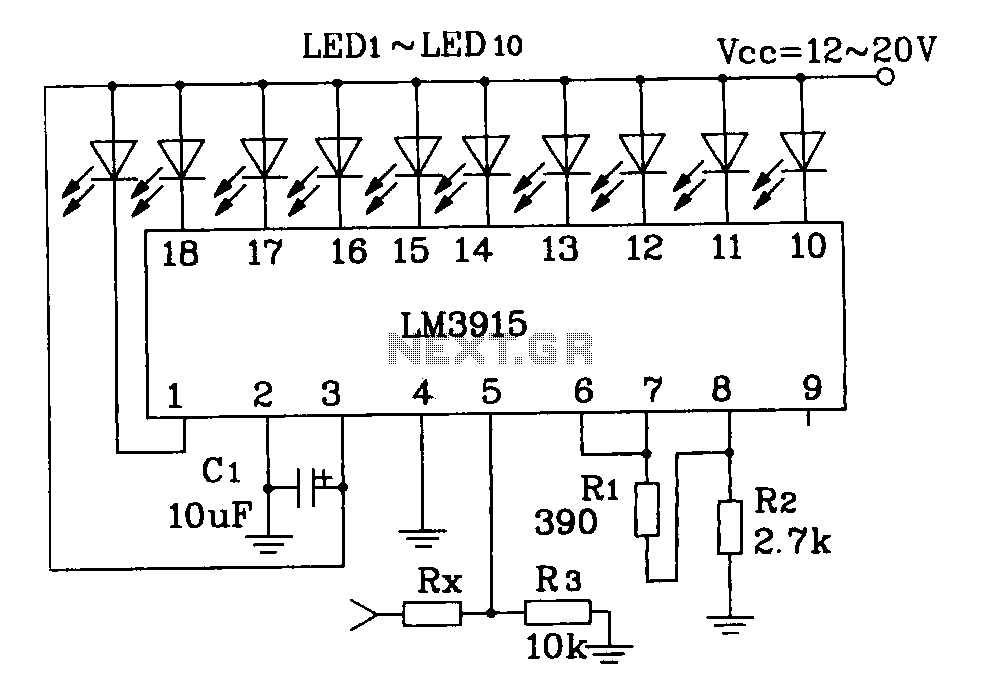
This document describes a simple LM3915 audio power meter circuit diagram. It notes that if the internal resistance of the speaker is 4 ohms, a resistor value of 10k ohms should be used for Rx. For an 8-ohm speaker,...
These small electronic lamps are quite practical and have a long lifespan. Approximately 40 years after Nick Holonyak invented the first LED, they have become nearly essential. Any dedicated electronics enthusiast typically keeps a few in their collection. Prior...
Frequently, there are situations where the need arises to utilize a Zener diode, yet the operational voltage is unknown. Often, the characteristics or type inscribed on the diode are not legible. Zener diodes are essential components in electronic circuits, primarily...