
Delayed ON LED
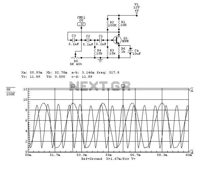
This circuit operates on the principle of a time delay using a capacitor and a resistor in combination with a transistor switch. Upon activation of the power supply, the capacitor C1 begins charging through the potentiometer R3. The charging time is determined by the RC time constant, which is the product of the resistance (R3) and the capacitance (C1).
As the capacitor charges, the voltage across it increases gradually. The transistor, which is configured in a common emitter mode, remains in the cutoff region until the voltage across the capacitor exceeds the base-emitter threshold voltage of the transistor. Once this threshold is surpassed, the transistor enters saturation, allowing current to flow through the LED, thus illuminating it.
The adjustable nature of R3 allows for fine-tuning of the delay period, making this circuit versatile for various applications requiring time delays. Increasing the resistance of R3 will extend the time it takes for the capacitor to charge to the necessary voltage, thereby increasing the delay before the LED turns on. Conversely, decreasing R3 will shorten the delay.
This simple LED delay circuit can be utilized in applications such as timers, alarms, or any device where a delayed activation is beneficial. The choice of capacitor value also plays a crucial role in determining the delay; larger capacitance will result in longer delays, while smaller capacitance will yield shorter delays.Here is very simple circuit in which the LED becomes ON only after a preset time the power supply is switched ON. When the power supply is switched on the transistor will be OFF. The capacitor now charges via the preset R3 and when the voltage across C1 is sufficient, the transistor switches ON and LED glows.
The ON delay depends on the value of P OT R3. You can increase the time delay by increasing the resistance of POT R3. 🔗 External reference
Related Circuits
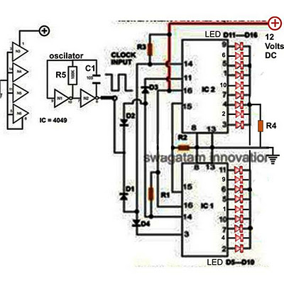
Decorative lights arranged in various moving patterns are visually appealing and have gained significant popularity in today's world. While more complex lighting arrangements may require the use of microcontroller ICs, simpler yet captivating light effects can be generated using...

A simple linear voltage-controlled amplifier can be constructed with one operational amplifier (op amp) and two junction field-effect transistors (JFETs). This amplifier can achieve an 80-dB dynamic control range with less than ±0.2% linearity error for 0 V. The described...

Designing a controller PCB for a 10x10 white LED matrix clock based on an ATmega328 AVR IC and a Maxim DS3234 SPI RTC. The challenge lies in controlling a custom non-standard 10x10 LED matrix. Initially, a Maxim MAX7219/7221 IC...
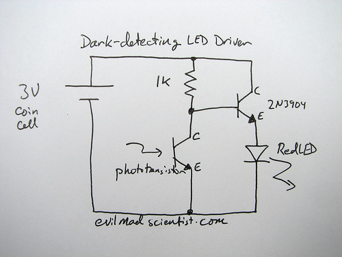
How can an LED be activated in low light conditions? This scenario, often referred to as the "nightlight problem," is applicable in various situations such as emergency lights, street lights, and even computer keyboard backlights. There are numerous solutions...
LEDs come in various sizes and shapes, with the most common being round-topped cylinders with diameters of either 3 mm or 5 mm. These sizes are often referred to as T1 (3 mm) and T1 (5 mm). The body...

A basic LED driver circuit consists of a 5-volt power source, a 2 kΩ potentiometer, and an LED. The LED is forward biased, with the manufacturer specifying a maximum current rating of 20 mA at a diode voltage drop...
Warning: include(partials/cookie-banner.php): Failed to open stream: Permission denied in /var/www/html/nextgr/view-circuit.php on line 713
Warning: include(): Failed opening 'partials/cookie-banner.php' for inclusion (include_path='.:/usr/share/php') in /var/www/html/nextgr/view-circuit.php on line 713