
10 watt amplifier for 18MHz
The described project involves the construction of a linear RF amplifier that is capable of transforming an input power of 0.55 to 3 watts into an output power of up to 10 watts. This amplifier is specifically designed to be compatible with QRP (Low Power) SSB (Single Sideband), CW (Continuous Wave), FM (Frequency Modulation), and AM (Amplitude Modulation) transmitters operating within the amateur radio bands of 15 and 17 meters. The amplifier operates from a 12-volt DC power supply, making it suitable for portable or mobile applications.
The design emphasizes a balance between output power and physical dimensions, allowing for a compact assembly that does not compromise performance. The completed amplifier is expected to deliver a clean and powerful output signal, enhancing the capabilities of QRP rigs, particularly under less-than-ideal radio conditions.
In terms of construction, special attention must be paid to the biasing of the amplifier's transistors to ensure optimal RF performance. Proper biasing is critical for achieving clean and accurate SSB modulation. The bias current for the transistor T1 should be set using a potentiometer (P1) to achieve a current of approximately ±35 mA flowing through T1. This adjustment is essential for maintaining the linearity of the amplifier and preventing distortion in the output signal.
Overall, this project not only serves as a practical application of RF amplification technology but also provides valuable experience in working with circuit biasing and modulation techniques relevant to amateur radio operations.This project and your efforts will provide you with a 0.55...3 watt input to easily 10 watt output. The two linear amplifiers are ment for use with QRP SSB/CW/FM/AM transmitters on the amateur bands 15 and 17 meters can be powered from a 12 volt DC supply. The design is a good balance between output power, physical size. The completed amplifier will reward the builder with a clean, more powerful output signal for a QRP rig when radio conditions become marginal.
Power amplifiers used in base stations require biasing for proper RF performance. BIAS has be applied to T1 to have clean proper and correct SSB modulation using this amplifier. Set P1 so +/- 35 mA current flows through T1. Depending on the type of transi 🔗 External reference
Related Circuits
The test beeper generates a sinusoidal signal with a frequency of 1,000 Hz, which is a standard test frequency for audio amplifiers. It utilizes a Wien-Bridge oscillator configuration, also referred to as a Wien-Robinson oscillator. The frequency-determining network comprises...
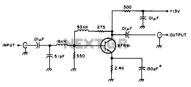
The amplifier delivers a gain of 10 dB across a frequency range of 10-600 MHz and features a 1-to-1 impedance match at 50 ohms. The BFR91 transistor exhibits a noise figure of 1 dB at 500 MHz. The circuit...
This microphone preamplifier utilizes the low-noise integrated circuit (IC) uA739. The circuit serves as an example of an effective design for preamplifying dynamic microphones. The IC contains two operational amplifiers. The uA739 is a precision integrated circuit known for its...
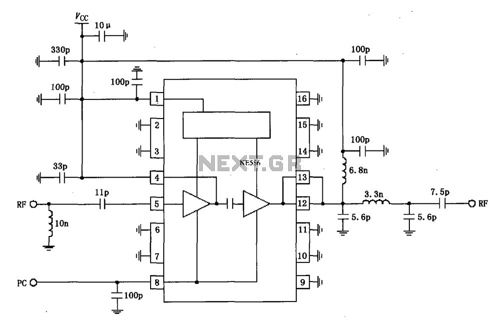
The RF2104 830MHz amplifier circuit operates as illustrated in the figure. A radio frequency (RF) signal enters through a 5-foot input, passes through a preamplifier, and is then amplified by an amplifier stage at the 12-pin output. The circuit...
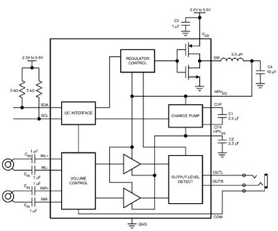
The LM48824's Stereo Headphone Amplifier, utilizing Class G architecture, enhances audio playback time for devices such as MP3 players and mobile TVs. Its adaptive power supply design allows for very low supply rails, effectively doubling power efficiency in comparison...
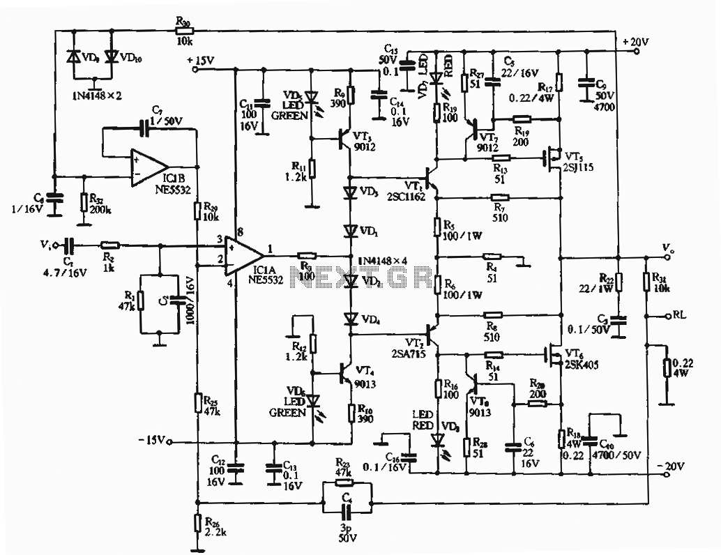
The circuit utilizes an FET amplifier configuration for output, incorporating an NE5532 operational amplifier powered by a 15V supply. The output stage features a FET that amplifies the voltage after passing through several stages. The bias circuit for the...