
100 MHz RF Oscillator Circuit

This circuit is designed to operate at a frequency of 100 MHz, utilizing a two-transistor configuration to achieve oscillation. The first stage consists of an electret microphone, which serves as the sound input device. The microphone converts acoustic energy into electrical signals, which are then amplified by the first transistor configured as a common-emitter amplifier. This amplification is crucial to ensure that the signal is strong enough to drive subsequent stages of the circuit.
The output from the collector of the first transistor is coupled to the base of the second transistor. This transistor plays a pivotal role in modulating the oscillation frequency of the circuit. The modulation occurs within a tank circuit, which comprises a 5-turn inductor coil and a variable capacitor (trim cap). The inductor and capacitor together form a resonant circuit that determines the oscillation frequency. By varying the junction capacitance of the second transistor, the effective capacitance in the tank circuit is altered, thereby modulating the resonant frequency.
The oscillation generated in this configuration can be used for various applications, including RF transmission and signal generation. The choice of components, such as the specific values of the inductor and capacitor, as well as the characteristics of the transistors, will significantly influence the performance and stability of the oscillator circuit. Proper biasing of the transistors is also essential to ensure that they operate in their active regions, thus maintaining linearity and minimizing distortion in the output signal.
Overall, this RF oscillator circuit exemplifies a straightforward yet effective design for generating high-frequency signals, with the electret microphone serving as an innovative input method for sound modulation.The following schematic diagram shows the design of a 100 MHz Radio Frequency RF Oscillator Circuit. The electrets microphone picks up and amplifies sound then fed it into the audio amplifier stage built around the first transistor. The output from the collector is fed into the base of the second transistor where it modulates the resonant frequency of the tank circuit (the 5 turn coil and the trim cap) by varying the junction capacitance of the transistor.
🔗 External reference
Related Circuits
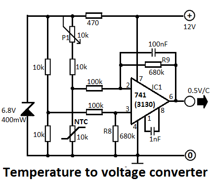
This simple temperature-to-voltage converter circuit allows for precise measurement of room temperature using an NTC resistor or thermistor. The temperature-to-voltage converter circuit typically employs a negative temperature coefficient (NTC) thermistor, which exhibits a decrease in resistance as temperature increases. This...

This design circuit serves as a converter utilizing the LM2623A ratio adaptive circuit to drive a digital camera motor. It generates 5 volts from input voltages that range between 1.8 and 4.5 volts. The circuit's duty cycle, while not...
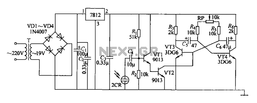
220V AC voltage is transformed by transformer T to 19V. After passing through a full-wave bridge rectifier and filter capacitor C, the voltage is regulated to DC using a 7812 voltage regulator. When the battery indicator light is illuminated,...
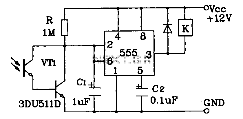
Darlington phototransistor type light-sensitive switch control circuit application. The Darlington type phototransistor serves as a sensitive element, capable of detecting low light levels for the detection of reflected light signals. The Darlington phototransistor circuit utilizes a pair of transistors configured...
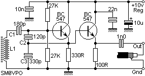
Create a basic RF oscillator. The circuit is very simple, so complex calculations will be omitted, and component selection will be simplified using calculators. For this example, the target frequency is 7 MHz. The circuit includes a transistor (TR1)...
This circuit generates a 10Hz sine wave using a minimal number of components, based on the specified component values. The active components are generic and can be substituted as needed. The passive component values determine the frequency and should...