
100KHz Crystal Oscillator
The design of the 100 kHz crystal calibrator circuit involves several key components and design considerations. The heart of the circuit is the 8 MHz microprocessor crystal, which serves as the frequency reference. This crystal is connected to the input of the 74HCT393 binary counter IC, which functions as a frequency divider. The 74HCT393 is a dual 4-bit binary counter that can divide the input frequency by a factor determined by the binary settings of its control pins.
To achieve the desired output frequency of 100 kHz, the 8 MHz signal from the crystal is fed into the first stage of the counter. The counter divides the input frequency by 80, which is accomplished by configuring the counter to count up to 80 before resetting. The output of the counter can then be connected to a digital display or used to drive other tuning circuits, providing a clear and precise frequency reference for the amateur transceiver.
Additional components may include bypass capacitors to stabilize the power supply to the ICs, as well as resistors and capacitors for setting the timing characteristics of the circuit. The layout of the circuit should minimize the length of the connections between components to reduce noise and ensure reliable operation. Proper grounding techniques should also be employed to prevent interference and improve the overall performance of the calibrator.
In summary, this 100 kHz crystal calibrator circuit provides a practical solution for amateur radio enthusiasts looking to modernize their vintage equipment. By leveraging readily available components, the circuit offers an effective means of achieving precise frequency calibration, enhancing the usability of older transceivers that rely on analog dials.There is a great deal of old amateur gear which many amateurs have decided to restore and bring back to life. While much of the early amateur transceivers work just fine they usually lack a digital readout and must rely on analog dials for tuning.
The problem of dial calibration is complicated by the non-linear effects of tuning capacitors. This month`s circuit is a 100Khz crystal calibrator using an inexpensive microprocessor crystal and CMOS IC`s which are readily available at Radio Shack. The main problem with building a 100Khz oscillator is the unavailability of 100Khz crystals. Even if you find a vendor willing to cut such a crystal for you, plan on paying $20 or more not including shipping charges.
The circuit uses an inexpensive 8MHz microprocessor crystal which can be easily obtained from most parts suppliers. Using a 74HCT393 binary counter IC, we can easily divide down the 8 MHz signal from our crystal into 100Khz or almost any frequency we need.
. 🔗 External reference
Related Circuits
The circuit was designed to create a frequency converter using a crystal oscillator for the conversion of 10 MHz to 1 MHz. It incorporates a 7404 hex inverter. The circuit functions as a frequency divider, utilizing a crystal oscillator to...
One of the simplest methods of metal detection is through a beat frequency oscillator. The circuit consists of two balanced oscillators: one provides a reference signal, while the other acts as the detector element. The frequency of the reference...
Adapting a failed Tesla coil into a crystal radio set for demonstration purposes has presented challenges, particularly with antenna size for optimal signal reception. It has been noted that an ideal AM antenna should range between 100 to 500...
The objective is to test a Wien bridge oscillator and ensure its proper functionality. There is a study of relevant material, but some concepts remain unclear. The Wien bridge oscillator is a type of electronic oscillator that generates sine waves....
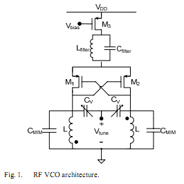
The oscillator is designed to tune from 1.8 GHz to 2 GHz for typical cellular telephony applications. An extended tuning range can be obtained by adjusting the ratio between the varactor capacitance and fixed capacitance in the tank. PMOSFETs...
Electronics tutorial about quartz crystal oscillators, including harmonic, overtone, Pierce oscillator, and crystal quartz oscillator circuits. Quartz crystal oscillators are vital components in modern electronics, providing stable frequency references for a variety of applications. They utilize the piezoelectric properties of...
Warning: include(partials/cookie-banner.php): Failed to open stream: Permission denied in /var/www/html/nextgr/view-circuit.php on line 713
Warning: include(): Failed opening 'partials/cookie-banner.php' for inclusion (include_path='.:/usr/share/php') in /var/www/html/nextgr/view-circuit.php on line 713