
100w inverter circuit
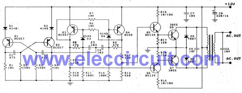
The 100-watt transistor inverter circuit operates by utilizing a combination of bipolar junction transistors (BJTs) to achieve the desired voltage conversion and frequency output. The input from a 12V battery is connected to the base of the first pair of BC558 transistors, which are configured in a push-pull arrangement. This arrangement allows for efficient switching, generating a square wave output. The RC network plays a crucial role in determining the oscillation frequency, which is initially set at 100Hz.
To achieve the final output frequency of 50Hz, the circuit includes a second stage with another pair of BC558 transistors that function as frequency dividers. This division is essential for applications requiring a standard 50Hz output, commonly used in household electrical systems.
The Darlington pair configuration, consisting of the BD139 and 2N3055 transistors, is employed to drive the transformer effectively. The Darlington arrangement enhances the current gain, allowing the circuit to drive the transformer with sufficient power to step up the voltage from 12V to 220V. The transformer is designed as a center-tapped unit, which facilitates the conversion of the square wave signal into an alternating current (AC) output suitable for powering standard appliances.
Overall, this inverter circuit is a practical solution for converting low-voltage DC power into high-voltage AC power, making it useful for various applications, including backup power supplies and portable power systems. The simplicity of the design, utilizing discrete transistors instead of integrated circuits, contributes to its reliability and ease of construction.This is transistor inverter circuit diagram 100watt it sizes are easy circuit. Because of use the all transistor, have no the integrated circuit. It performs to modify from battery 12V be 220V 50Hz signal square wave. By the circuit works with transistor BC558 x 2pcs and RC assemble the circuit produces 100HZ frequency from that time. There is the transistor BC558 2 again, build the circuit divides by 2 times frequency be left 50Hz frequencies from that time. There is the transistor BD139 and 2N3055 each other be Darlington for drive AC transformer 12V CT 12V : 220V, enhance ac voltage 12V from be 220V 50HZ fully be usable next.
The detail is other see in inverter circuit diagram. 🔗 External reference
Related Circuits
The following circuit illustrates a Repeating Interval Timer Circuit Diagram. This circuit is based on the CMOS 4060 integrated circuit (IC). Features include a 6-pin output. The Repeating Interval Timer Circuit utilizing the CMOS 4060 IC is designed to generate...
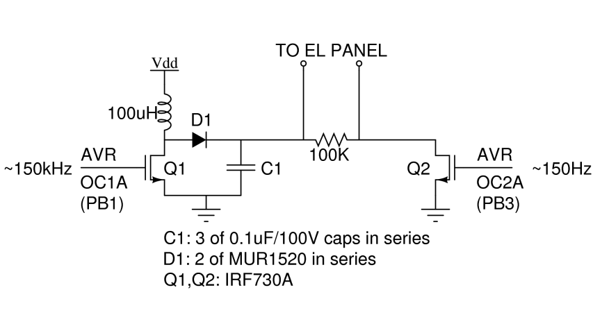
There are two primary types of backlights for LCDs: LEDs, which stands for light-emitting diodes, and EL, which stands for electroluminescent. EL backlights are generally more efficient and provide more uniform lighting compared to LED backlights, but they require...
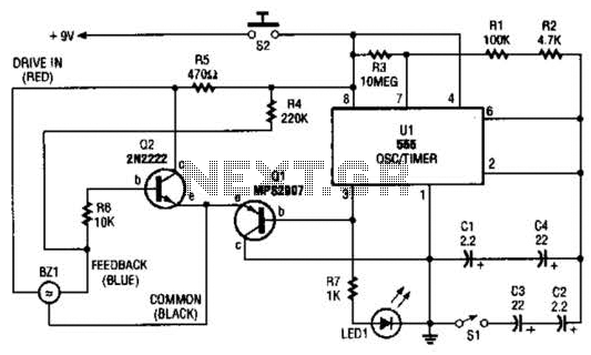
The electronic darkroom timer is constructed using a 555 oscillator/timer, a pair of general-purpose transistors, a buzzer, and an LED. The 555 timer (U1) is set up as an astable multivibrator, functioning as a free-running oscillator. The frequency of...
Delay electronic doorbell circuit - touch doorbell amplifier circuit The delay electronic doorbell circuit is designed to provide a user-friendly interface for doorbell activation, utilizing a touch-sensitive amplifier circuit. This circuit typically incorporates a touch sensor that detects user interaction,...

This is a design circuit diagram of a versatile FM transmitter. This circuit does not include a coil and is simple and easy to assemble. It operates based on gate logic concepts. The circuit features a buffer gate N1...
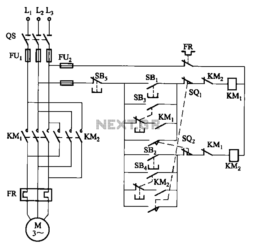
The circuit depicted in Figure 3-27 features a jog function that allows for precise adjustments of moving components. In the figure, SB3 and SB4 represent the forward jog and reverse jog buttons, respectively. When the SB3 button is pressed,...