
Repeating Interval TimerCircuit Based On The CMOS4060 IC

The Repeating Interval Timer Circuit utilizing the CMOS 4060 IC is designed to generate precise timing intervals suitable for various applications, including pulse generation and timing control in electronic devices. The CMOS 4060 is a versatile IC that combines a binary counter and an oscillator, enabling it to produce a wide range of frequencies based on external resistor and capacitor components.
In this circuit, the oscillator function is achieved by connecting a resistor and capacitor to the appropriate pins of the CMOS 4060. The frequency of oscillation can be adjusted by varying the resistance and capacitance values, allowing for flexibility in timing intervals. The output from the oscillator is fed into the binary counter section of the IC, which divides the frequency down to generate specific time intervals.
The 6-pin output feature of the CMOS 4060 allows for multiple output signals, which can be utilized to drive other components such as LEDs, relays, or other digital logic circuits. This capability makes the circuit suitable for applications that require repetitive timing signals or pulse outputs.
For optimal performance, it is essential to select the resistor and capacitor values carefully to achieve the desired timing intervals. Additionally, the power supply voltage should be within the specified range for the CMOS 4060 to ensure reliable operation. Proper decoupling capacitors may also be included in the design to minimize noise and enhance stability.
Overall, the Repeating Interval Timer Circuit based on the CMOS 4060 IC provides a robust solution for generating repeatable timing intervals, making it an invaluable component in various electronic applications.The following circuit shows about Repeating Interval Timer Circuit Diagram. This circuit based on the CMOS4060 IC. Features: 6 pin output, IC .. 🔗 External reference
Related Circuits
The following circuit illustrates a stepper motor controller based on the PIC16F84A integrated circuit. It features a transistor used for driving the motor. The stepper motor controller circuit utilizes the PIC16F84A microcontroller, which is a popular choice for controlling stepper...

This is a simple light-running circuit synchronized with music. The circuit is straightforward, operating in mono, and requires only a few components. It can be connected to the output of a CD player. The described circuit utilizes a basic audio...

This is one of the most accurate and simplest LC inductance/capacitance meters available, which can be easily constructed by an individual. This LC meter is capable of measuring very small inductances ranging from 10 nH to 1000 nH, 1...
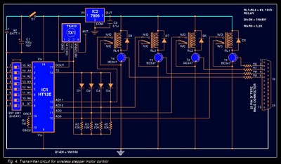
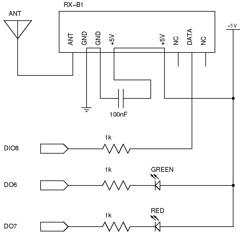
Stepper motors are widely used in applications such as process control, machine tools, and robotics. In particular, remote control of stepper motors is essential in robotics and process control. This document provides the circuit diagrams for both the transmitter...
The documentation and code cleaning for the Jaycar Thermor/BIOS branded wireless weather station receiver has been completed. The code is based on the Practical Arduino weather station receiver project. The process involved analyzing the RF signal from the weather...

This circuit features an adjustable output timer that can re-trigger at specified intervals. The output duration can range from a fraction of a second to over half an hour, with the ability to repeat at consistent intervals from seconds...