
LCD Backlight Electro luminescent Inverter
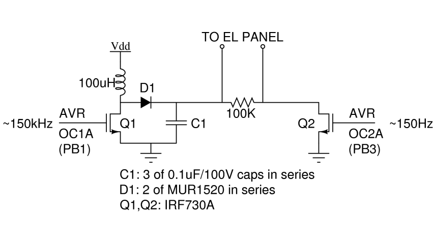
The circuit operates by leveraging the properties of inductors and MOSFETs to generate the necessary high voltage for the electroluminescent backlight. The inductor, when energized, stores energy in its magnetic field. Upon opening the switch, the sudden change in current induces a high voltage spike across the inductor. This voltage is then rectified and smoothed by the peak detector configuration of diode D1 and capacitor C1, ensuring that the electroluminescent panel receives a stable DC voltage.
The choice of components, particularly the high-voltage rated MOSFETs and capacitors, is critical in ensuring reliable operation and preventing component failure. The use of multiple capacitors in series not only provides the necessary voltage rating but also allows for flexibility in component selection. The AVR microcontroller plays a vital role in controlling the brightness of the electroluminescent panel through frequency modulation, allowing for dynamic adjustment of the display's illumination.
This circuit design exemplifies the integration of high-voltage techniques with microcontroller-based control systems, showcasing the ability to drive complex lighting solutions with precision and efficiency. Proper attention to component ratings, circuit layout, and operational parameters is essential for achieving optimal performance in electroluminescent backlight applications.There are two major types of backlights for LCDs: LEDs, which stands for light emitting diode, or EL, which stands for electroluminescent. EL backlights tend to be more efficient and have more uniform lighting than LED ones, but they require some tricky circuitry to drive.
If you`ve heard of Organic LED displays, or OLEDs, that`s basically an arra y of electroluminescent strips shunk down to the size of individual pixels. Every kit shipped before 4/07/2009 has an LCD which actually includes an electroluminescent backlight. Kits shipped on 4/07/2009 or newer have an LED-based backlight, so this video does not apply. Electroluminescent backlights are hard to drive because they actually require about 100 volts AC at around 150 Hz, and we`re just running our logic off 5 volts DC.
But we can use an inductor to generate these high voltages. After a current is allowed to build up in the inductor, the switch is opened. The fundamental device law of any inductor is V=L*dI/dt, where dI/dt is the change in current per time. So if the current is asked to change from something to zero basically instantly, a huge voltage will be present.
(For our actual circuit, we measured a 300V peak and roughly 100mA of peak inductor current, which means dI/dt=3, 000, 000 Amps/second, or switching off in about 33ns! This matches well to the 22ns rise time listed on the IRF730A datasheet. ) Whenever the voltage on the unconstrained end of the inductor is greater than the voltage across C1, diode D1 lets charge flow and further charge C1.
This is basically a peak detector, finding the maximum to make a smooth DC signal. The 100K resistor guarantees that if Q2 is open, the electroluminescent panel will have zero voltage across it, because the 100K resistor will discharge the very small capacitance (not shown) in the electroluminescent panel itself. The electroluminescent panel sees the high voltage across it only when Q2 is pulling the right EL wire down to ground.
The AVR microcontroller generates two square waves from its Timer 1 and Timer 2 units. The brightness can be varied most directly by adjusting the frequency driving Q1. A faster frequency means there is less time for current to build up in the inductor before it switches off, leading to a smaller dI/dt and therefore a smaller voltage spike. We need two switches, Q1 and Q2, for our circuit. These MOSFETs in particular can withstand 400V before undergoing drain-source breakdown. This breakdown voltage is important, because it means that at a particular voltage (when the MOSFET is OFF), the drain-source will begin to conduct even though the gate is being held low.
Since this is something we clearly want to avoid (as it`d discharge our capacitor at the wrong time), we need to find special MOSFETs like these with particularly high breakdown voltages. These can withstand 200V of repetitive reverse voltage before breakdown, so we decided to use 2 of them in series to provide a total of 400V of reverse breakdown protection.
(We originally used a 1N914 but destroyed it due to the high voltages imposed as we were testing the limits of our circuit. ) We didn`t have any high voltage capacitors on hand, so we used three equal capacitors in series to get a voltage rating of 300V - the lowest in our system.
You may know that capacitors in series produce a smaller overall capacitance, but that`s OK here, because we really just need the higher voltage limit. So overall, we`ll have 33. 3nF of capacitance with a 300V limit. This circuit draws too much current to run off the 9V battery for very long. We used a 12V DC wall transformer, cutting off the connector. Measure the voltage at the end, especially to get +/- correct. Then, just plug it into the NerdKit where you currently have the 9V battery clip. Anything roughly in the 7V to 20V range will work. Note: One end of the inductor is connected to "Vdd" and not +5V. In this case, connect it directly to 🔗 External reference
Related Circuits
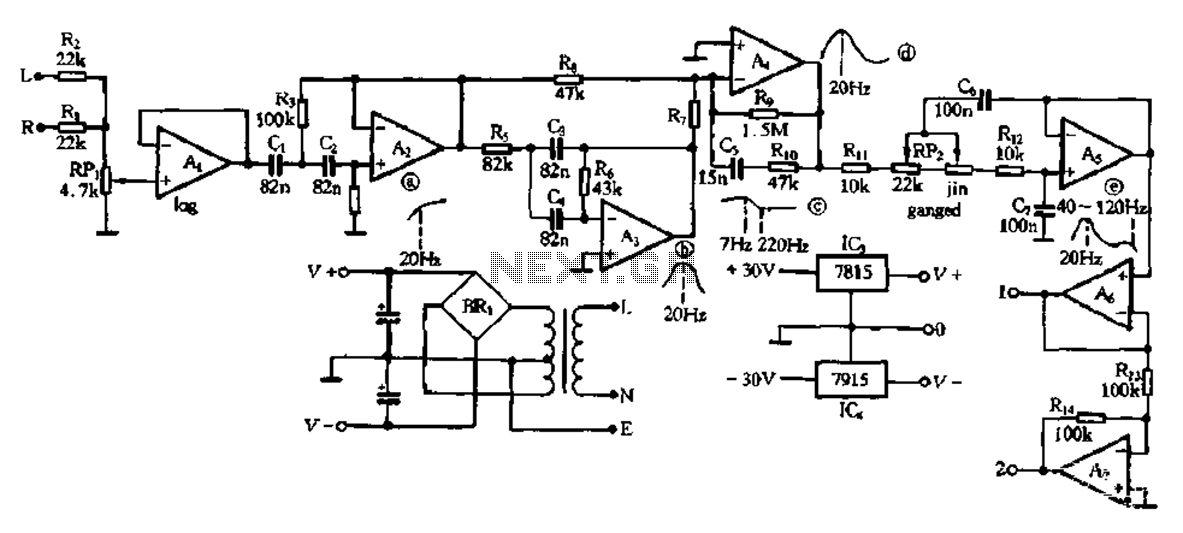
This electronic bass equalizer circuit utilizes two quad operational amplifiers, specifically the TL084 high-speed operational amplifier. The circuit includes left and right channels that are mixed through resistors R1 and R2, and features a total bass level adjustment potentiometer...
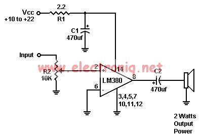
A simple audio amplifier can be designed using the LM380 along with a few external components. This amplifier features a wide supply voltage range, an input impedance of 150 kΩ, low distortion, and a current capability of 1.3 A. The...
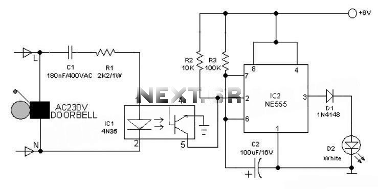
This 6V battery-operated doorbell light circuit can be connected in parallel with any existing AC 230V doorbell. When the doorbell switch is pressed, the bell sounds as usual, and the AC mains supply available across the doorbell is routed...
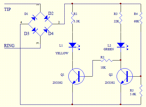
Phone In Use Indicator Electronics Project using 5 resistors, 2 NPN transistors, 4 diodes, and 2 light-emitting diodes. The Phone In Use Indicator is an electronic project designed to visually indicate when a telephone line is active. This circuit employs...
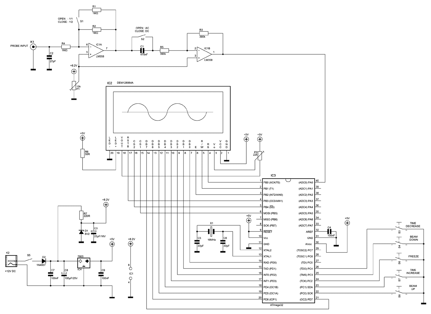
A few months ago as I was surfing on the net, I saw an oscilloscope based on PIC18F2550 microcontroller and a KS0108 controller based graphical LCD. That was Steven Cholewiak's web site. I had never seen before so amazing...
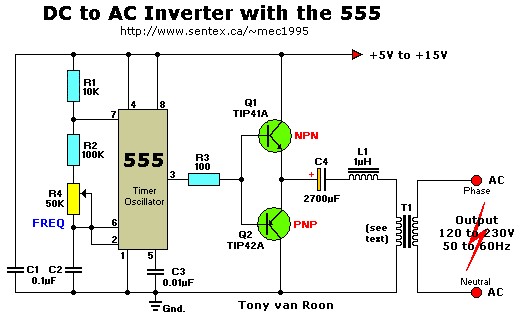
This simple 12V DC to 220V AC inverter circuit generates an AC output at line frequency and voltage. The 555 timer is configured as a low-frequency oscillator, adjustable over the frequency range of 50 to 60 Hz via the...
Warning: include(partials/cookie-banner.php): Failed to open stream: Permission denied in /var/www/html/nextgr/view-circuit.php on line 713
Warning: include(): Failed opening 'partials/cookie-banner.php' for inclusion (include_path='.:/usr/share/php') in /var/www/html/nextgr/view-circuit.php on line 713