
100W RF Amplifier Circuit With BLY94 Transistor

The 100W RF amplifier circuit utilizing the BLY94 transistor is designed to amplify radio frequency signals efficiently. The BLY94 is a high-performance RF power transistor known for its capability to handle high frequencies and provide substantial output power. In this configuration, it is essential to ensure proper biasing and load matching to maximize efficiency and minimize distortion.
The circuit typically includes an input stage that may consist of a matching network to couple the RF signal into the base of the BLY94. This matching network often employs inductors and capacitors to achieve the desired impedance transformation. The inductor plays a crucial role in tuning the circuit to resonate at the desired frequency, which enhances the amplifier's performance.
The output stage of the amplifier is designed to deliver the amplified RF signal to the load, which could be an antenna or another stage of amplification. It is vital to include appropriate filtering components to suppress unwanted harmonics and ensure that the output signal remains clean and within the specified frequency range.
Thermal management is another critical aspect of the design, as the BLY94 can generate significant heat during operation. Adequate heat sinking and possibly active cooling solutions should be incorporated to prevent thermal runaway and ensure reliable operation.
Overall, the design of the 100W RF amplifier with the BLY94 transistor requires careful consideration of component selection, circuit layout, and thermal management to achieve optimal performance in RF applications.This is a part of a 100W RF amplifier. This circuit built based on RF power transistor BLY94. Component: BLY94 Transistor, Inductor, .. 🔗 External reference
Related Circuits
.gif)
This article includes a list of references, but its sources remain unclear due to insufficient inline citations. More precise citations are needed to improve this article. Valves, also known as vacuum tubes, exhibit very high input impedance (nearly infinite...

This circuit produces a soft turn-on for halogen lamp filaments upon powering up. The MOSFET used is a BUZ10, which has a resistance of 0.2 ohms. Resistors R1, R2, and capacitor C1 set the turn-on rate, while diode D1...
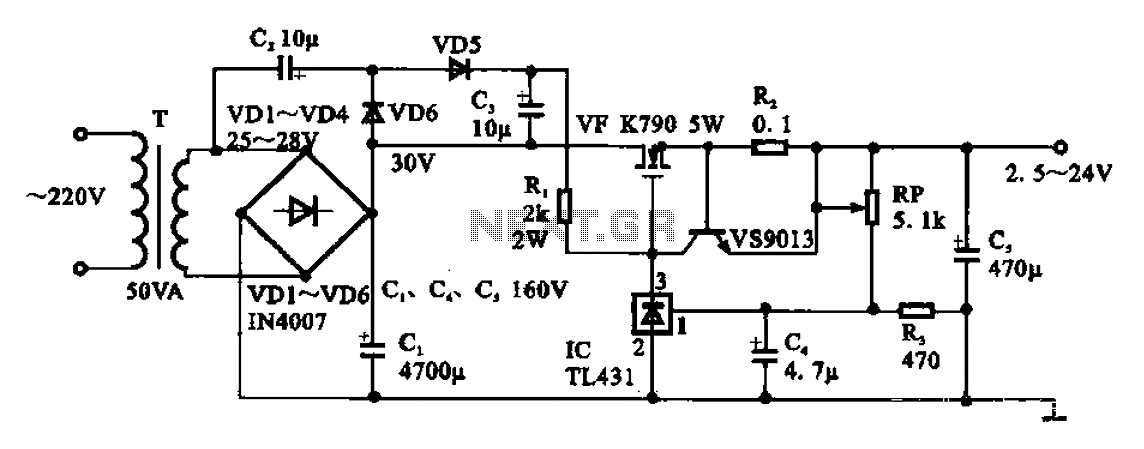
An adjustable DC power supply circuit is presented, consisting of a step-down transformer (T), a rectifier bridge (VD1 to VD4), and additional components. The voltage regulator circuit includes an adjustment potentiometer (RP, 5.1 kΩ), allowing the output voltage to...

An advantage of a photogate over a sound trigger is that the former activates based on the exact position of the object that interrupts the beam. For instance, the shape of a snapped elastic cord can be captured as...

This simple FM wireless microphone transmitter can transmit speech over a short range. It can be used as a simple cordless microphone. The circuit uses two. The FM wireless microphone transmitter is designed for short-range audio transmission, making it suitable...

There are many circuits for low voltage regulators. For higher voltages, such as supplies for valve circuits, the situation is different. Low voltage regulators are widely utilized in electronic circuits to provide a stable output voltage from a varying input...