
Valve audio amplifier technical specification
.gif)
Another implication of valve operation is that since the output of one stage is typically around 100 V offset from the input of the subsequent stage, direct coupling is generally impractical. Stages must be coupled using capacitors or transformers. Capacitors minimally affect amplifier performance, while interstage transformer coupling can introduce distortion and phase shift, leading to its avoidance in high-quality applications since the 1940s. Transformers also contribute additional costs, bulk, and weight.
The following circuits are simplified conceptual designs; real-world circuits require a smoothed or regulated power supply, filament heaters (depending on whether the selected valve types are directly or indirectly heated), and often bypassed cathode resistors. The basic gain stage for a valve amplifier is the auto-biased common cathode stage, where an anode resistor, the valve, and a cathode resistor create a potential divider across the supply rails. The valve's resistance varies based on the voltage on the grid relative to the cathode voltage. In the auto-bias configuration, the operating point is established by setting the DC potential of the input grid to zero volts relative to ground using a high-value "grid leak" resistor. The anode current is determined by the grid voltage in relation to the cathode, which in turn depends on the resistance chosen for the cathode branch of the circuit. The anode resistor serves as the load for the circuit and is typically 3-4 times the anode resistance of the valve type in use. The output from this circuit is the voltage at the junction between the anode and the anode resistor, varying with changes in the input voltage and dependent on the voltage amplification factor of the valve (denoted as "mu") and the selected values for the circuit elements.
Two triodes may be configured with their cathodes coupled together to form a differential pair. This arrangement can effectively cancel common-mode signals (equal on both inputs) and, when operated in class A, can largely reject supply variations, as these affect both sides of the differential stage equally. The total current drawn by the stage remains nearly constant, meaning if one side draws more current at a given moment, the other side compensates by drawing less, minimizing supply rail sag and potential interstage distortion.
In a push-pull output stage, two power valves (which may be triodes or tetrodes) are differentially driven to form a configuration that drives a push-pull transformer load. This output stage utilizes the transformer core more efficiently than a single-ended output stage. A long tail serves as a constant current load for the shared cathode feed to the differential pair. Theoretically, a more constant current can linearize the differential stage. The long-tail pair can also function as a phase splitter, commonly employed in guitar amplifiers (referred to as the "phase inverter") to drive the power section. Alternatively, the concertina configuration uses a single triode as a variable resistor to achieve similar phase-splitting functionality.This article includes a list of references, but its sources remain unclear because it has insufficient inline citations. Please help to improve this article by introducing more precise citations. Valves (also known as vacuum tubes) are very high input impedance (near infinite in most circuits) and high-output impedance devices.
They are also hig h-voltage / low-current devices. The characteristics of valves as gain devices have direct implications for their use as audio amplifiers, notably that power amplifiers need output transformers (OPTs) to translate a high-output-impedance high-voltage low-current signal into a lower-voltage high-current signal needed to drive modern low-impedance loudspeakers (cf. transistors and FETs which are relatively low voltage devices but able to carry large currents directly).
Another consequence is that since the output of one stage is often at ~100 V offset from the input of the next stage, direct coupling is normally not possible and stages need to be coupled using a capacitor or transformer. Capacitors have little effect on the performance of amplifiers. Interstage transformer coupling is a source of distortion and phase shift, and was avoided from the 1940s for high-quality applications; transformers also add cost, bulk, and weight.
The following circuits are simplified conceptual circuits only, real world circuits also require a smoothed or regulated power supply, heater for the filaments (the details depending on if the selected valve types are directly or indirectly heated), and the cathode resistors are often bypassed, etc. The basic gain stage for a valve amplifier is the auto-biased common cathode stage, in which an anode resistor, the valve, and a cathode resistor form a potential divider across the supply rails.
The resistance of the valve varies as a function of the voltage on the grid, relative to the voltage on the cathode. In the auto-bias configuration, the "operating point" is obtained by setting DC potential of the input grid at zero volts relative to ground via a high-value "grid leak" resistor.
The anode current is set by the value of the grid voltage relative to the cathode and this voltage is now dependent upon the value of the resistance selected for the cathode branch of the circuit. The anode resistor acts as the load for the circuit and is typically order of 3-4 times the anode resistance of the valve type in use.
The output from the circuit is the voltage at the junction between the anode and anode resistor. This output varies relative to changes in the input voltage and is a function of the voltage amplification of the valve "mu" and the values chosen for the various circuit elements. Two triodes with the cathodes coupled together to form a differential pair. This stage has the ability to cancel common mode (equal on both inputs) signals, and if operated in class A also has the merit of having the ability to largely reject any supply variations (since they affect both sides of the differential stage equally), and conversely the total current drawn by the stage is almost constant (if one side draws more instantaneously the other draws less), resulting in minimal variation in the supply rail sag, and this possibly also interstage distortion.
Two power valves (may be triodes or tetrodes) being differentially driven to form a push pull output stage, driving a push pull transformer load. This output stage makes much better use of the transformer core than the single-ended output stage. A long tail is a constant current (CC) load as the shared cathode feed to a differential pair. In theory the more constant current linearises the differential stage. The long-tail pair can also be used as a phase splitter. It is often used in guitar amplifiers (where it is referred to as the "phase inverter") to drive the power section.
As an alternate to the long-tail pair, the concertina uses a single triode as a variable res 🔗 External reference
Related Circuits
%2B2%2BCH%2Bby%2BIC%2B%2BNE5532%2Bor%2BLF353.jpg)
This is a microphone preamplifier circuit model 2 CH. The circuit utilizes integrated circuits NE5532 or LF353 to amplify the sound signal from a dynamic microphone, increasing the power level for subsequent input into a stereo power amplifier. This...
One of the most notable RF amplifiers documented is Wes Hayward's post-mixer amplifier in the Progressive Communications Receiver. It is recognized as a highly effective high-level RF amplifier, operating with a standing current of 50 mA, which allows it...
A 6-watt audio amplifier circuit utilizing the TDA2613 integrated circuit is presented. The TDA2613, produced by Philips Semiconductors, is a high-fidelity audio amplifier IC. This component is designed to be click-proof when switched on or off, resistant to short...
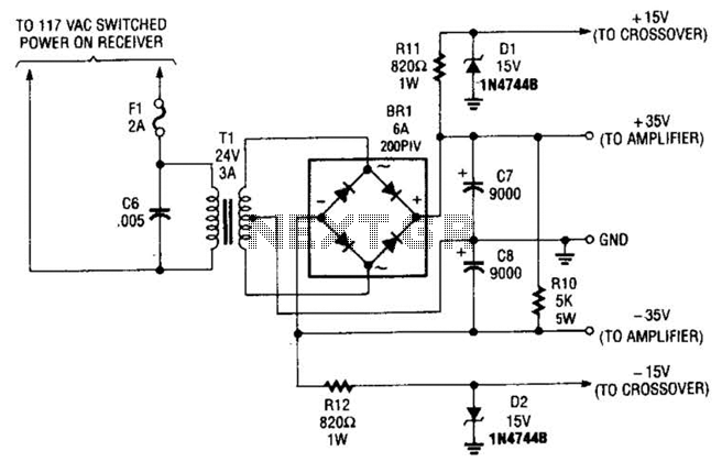
This power supply is designed to power a 100-W low-frequency amplifier and is capable of supporting various mono or stereo amplifiers within the medium power range, specifically those that require 30 to 35 V. The power supply circuit is engineered...
The amplifier circuit utilizes negative current feedback, which ensures that the load current is primarily influenced by the input signal rather than the loudspeaker's impedance. The inductor current from the loudspeaker generates a voltage across resistor R7, which is...
It is widely recognized that while a large loop feedback from the amplifier output stage to the preceding stage can enhance frequency response and reduce harmonic distortion indicators in an amplifier, it may adversely affect the transient characteristics and...
Warning: include(partials/cookie-banner.php): Failed to open stream: Permission denied in /var/www/html/nextgr/view-circuit.php on line 713
Warning: include(): Failed opening 'partials/cookie-banner.php' for inclusion (include_path='.:/usr/share/php') in /var/www/html/nextgr/view-circuit.php on line 713