
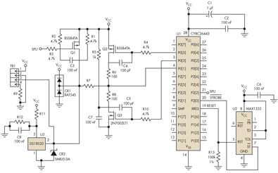
Interfacing circuit
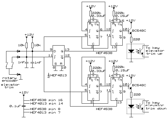
The circuit described integrates a rotary encoder with a keyboard interface through pulse width modulation techniques to ensure reliable key presses. The rotary encoder, when turned, generates pulses that are processed by a D-flip-flop, which determines the direction of rotation. This information is then utilized to trigger two one-shot circuits that reshape the pulses to meet the keyboard controller's requirements. The choice of using an opto-coupler instead of a relay minimizes noise and allows for cleaner signal transmission. The use of timing components, such as resistors and capacitors, ensures that the output pulses are of adequate duration to be recognized by the keyboard controller, thereby maintaining stable operation. The addition of an emitter follower transistor enhances the current drive capability for the opto-coupler, ensuring that the circuit can handle the demands of rapid rotary encoder operation. The potential for false pulses indicates the need for further refinement, possibly through the incorporation of capacitors to filter out noise. Overall, this design demonstrates a practical application of digital logic and signal processing techniques in interfacing mechanical components with electronic systems, providing a reliable solution for applications requiring precise control inputs.After doing some experiments with the rotary encoder directly connected across the keyboard switches, I found that the keyboard controller IC (an old Intel P8049AH in my case) cannot detect too narrow pulses. (I checked this by rotating the encoder fast and checking with Notepad to see the key output). If key ON pulses are less than 20 msec, the k ey press is ignored or unstable. I also found that the time between two key presses cannot be too short either: The OFF time between two ON pulses needs to be more than 20 msec as well. This means that the rotary switch outputs need to undergo some pulse width modification before they can drive the keyboard.
As mentioned before, the keyboard switches do not have a common ground, and therefore are best driven by means of a relay or Opto-coupler. For repeated switching, relays are too noisy. In this case, Opto-couplers are preferred. The drawing above shows the rotary switch action (slow and fast turning) and required keyboard switch action to maintain stable key recognition.
When the rotary encoder is turned very fast, the buffer circuit in between maintains the speed that the keyboard controller still can follow. In the above circuit, the D-flipflop (one-half of CMOS HEF4013 IC) determines which direction the rotary encoder turns.
When turning in one direction, HEF4013 Q output will be high and Q will be low. When turning the other direction, the situation reverses. When high, these outputs Q and Q enable upper and lower one-shot circuits build with IC HEF4538. These one shot circuits are used to re-shape the pulses from the rotary encoder as shown in the drawing. Since Q and Q are each others inverse, only one section will drive the keyboard via one opto-coupler, depending on the turning direction.
For info on the IC ’s do a search at. The first one-shot has a twice longer time than the second. Both are triggered by the pulses of one of the switches of the rotary encoder. The first negative going pulse will produce a pulse at both Q outputs. The pulse time duration is equal to R*C as connected to the timing pins. The Q output pulse of the first one-shot lasts 0. 07sec, that of the second 0. 033sec. As long as the first one-shot output is high, neither one-shot can be re-triggered by additional pulses of the rotary encoder. Even if the encoder is turned very fast, the opto-coupler is driven with a pulse that is at least 0. 033sec high and 0. 032sec low. Since CMOS IC ’s cannot deliver a lot of current, I added an emitter follower to drive the Opto-coupler.
BC548C (or BC547) is a standard small signal NPN transistor. (see ) The circuit is not perfect, as there are occasionally false pulses from the other section while tuning one direction. Adding 1 nF (0. 001uF) capacitors at the rotary switches may help somewhat. (I did not use them). For elevator trim, I found the performance satisfactory. In principle, the same circuit can be used for rudder trim. Since rudder trim is normally not rotated very fast, some simplifications can be made: I deleted the trigger inhibit after initial ON pulse, thereby saving one IC.
The rotation direction detect circuit can be made from the other half of the HEF4013 IC. The circuit is shown below. (Although you loose some pulses from the original encoder output, the final pulse count is the most you can get via the keyboard, and works much better than w/o pulse shape buffer). 🔗 External reference
Related Circuits
An anti-theft car audio system circuit is depicted, powered by a 12V DC supply from the car battery. Upon closing switch S1, the light-emitting diode in optocoupler IC1 activates, causing the phototransistor to conduct. This results in a high-level...
A simple USB FM transmitter that can be used to play audio files from an MP3 player or computer on a standard VHF FM radio by connecting it to a USB port. The circuit does not require any coils...
The amplifier's gain is nominally 20 dB. Its frequency response is primarily influenced by the values of a few components, mainly C1 and R1. The schematic diagram's component values yield a frequency response of ±3.0 dB from approximately 120...
Temperature indicators and temperature-based products have garnered significant interest due to their numerous applications and various possible solutions, each presenting unique advantages and disadvantages. This concept focuses on a sensor interface that delivers high accuracy while minimizing board space....
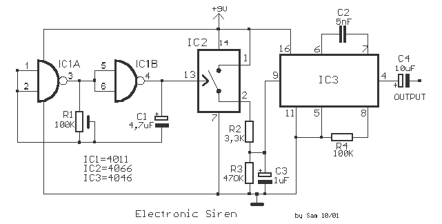
With this circuit we can create a altered sound of siren. The oscillator IC1a-b is constituted by two gates NAND, oscillating in very low frequency. This oscillation drive the IC2, that is a electronic switch, which opens and closes...
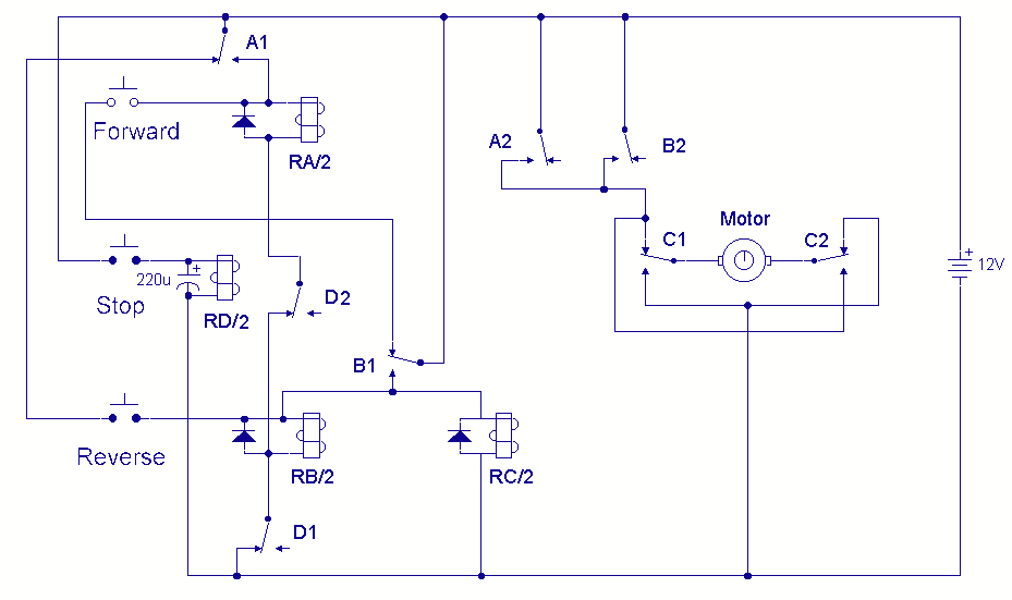
A DC motor reversing circuit using non-latching push button switches. Relays control forward, stop, and reverse action, and the motor cannot be switched from forward to reverse unless the stop switch is pressed first. The described circuit employs a system...