
110dB Beeper Circuit
The beeper circuit operates effectively by utilizing the properties of the 74C14 CMOS IC, which provides robust performance in generating square wave signals suitable for driving piezoelectric devices. The astable oscillator configuration allows for continuous oscillation, which is crucial for producing sound. The choice of operating frequency, specifically set to five times lower than the resonant frequency of the piezoelectric element, maximizes sound output due to resonance effects. The feedback mechanism is essential for stabilizing the oscillation frequency, ensuring that the piezoelectric device operates efficiently.
The cross-wiring of the inverter sections introduces a differential drive signal, which enhances the voltage swing across the piezoelectric element, thus increasing the sound pressure level generated. The additional astable oscillator serves a dual purpose; it can modulate the sound output at a lower frequency, providing a pulsing effect if desired. However, for applications requiring a steady tone, the modulation can be bypassed by eliminating the associated circuitry.
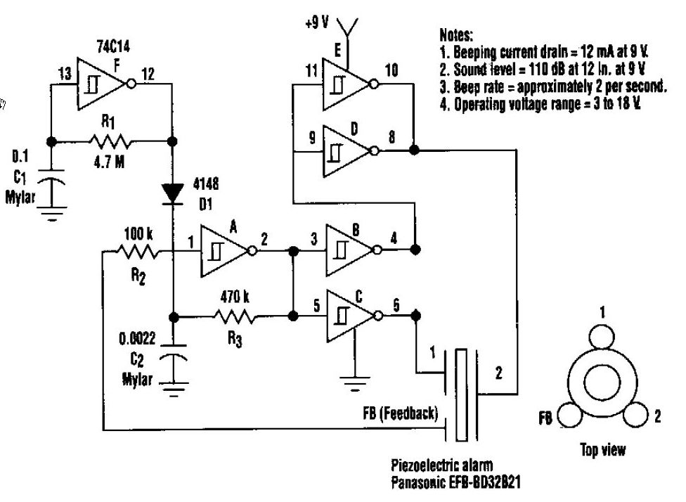
This circuit design showcases the versatility of CMOS technology in audio applications, particularly in generating high-decibel sound levels from a compact and efficient setup. The careful consideration of frequency, feedback mechanisms, and drive configurations contributes to the effective performance of the beeper circuit, making it suitable for various signaling applications.This beeper circuit will generate an car-splitting 110dB from 9V. The setup uses a single 74C14 (CD40106B) CMOS hex inverting Schmitt-trigger IC, which must be used with a piezoelectric device with a feedback terminal. The feedback terminal is attached to a central region on the piezoelectric wafer. When the beeper is driven at resonance, the feed back signal peaks. One inverter of the 74C14 is wired as an astable oscillator. The frequency is chosen to be 5 times lower thant the 3, 2KHz resonant frequency of the piezoelectric device. Feedback from the third pin of the beeper reinforces the correct drive frequency to ensure maximum sound output.
Four other inverter sections of the IC are wired to form two separate drivers. The output of one section is cross-wired to the input of the second section. The differential drive signal that results produces about 18Vpp when measured across the beeper. The last inverter section is wired as a second astable oscillator with a frequency of about 2 Hz. It gates the main oscillator on and off through a diode. For a continous tone, the modulation circuit can be deleted. 🔗 External reference
Related Circuits
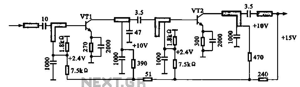
An IF pre-amplifier circuit is presented in a distributed-parameter microstrip configuration. It operates within the frequency range of 950 to 1,470 MHz. The output impedance is approximately 75 ohms. The power supply for the circuit is connected to the...
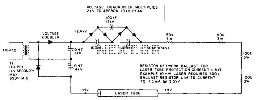
This circuit delivers a peak voltage of 10 kV, while limiting the current to 7.5 mA at 2 kV. The resistors included in the design serve the purpose of ballasting. Additionally, the starting circuit is unable to sustain the...
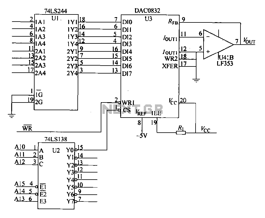
The DAC0832 is depicted in Figure 27-13 as a single-phase circuit connected to the 8086 CPU. The internal 8-bit data input of the DAC0832 must be interfaced with the CPU and the D/A converter interface circuits for data transmission,...
A switch that is controlled by its ambient temperature operates without human intervention, except during the assembly of the electronic thermostat. This thermally controlled switch has numerous practical applications. For instance, if the internal temperature of a computer rises...
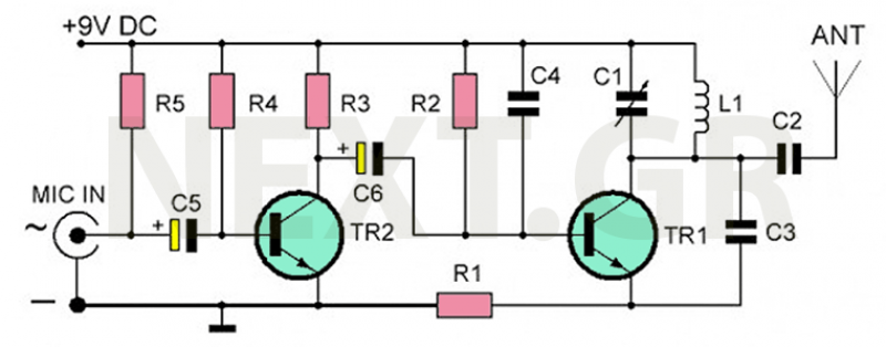
The recommended transmitter is straightforward to construct and suitable for beginners. Despite its simple design and compact size, it delivers remarkable performance. It operates for 12-15 hours on a 9-volt battery and has a transmission range of 100 to...
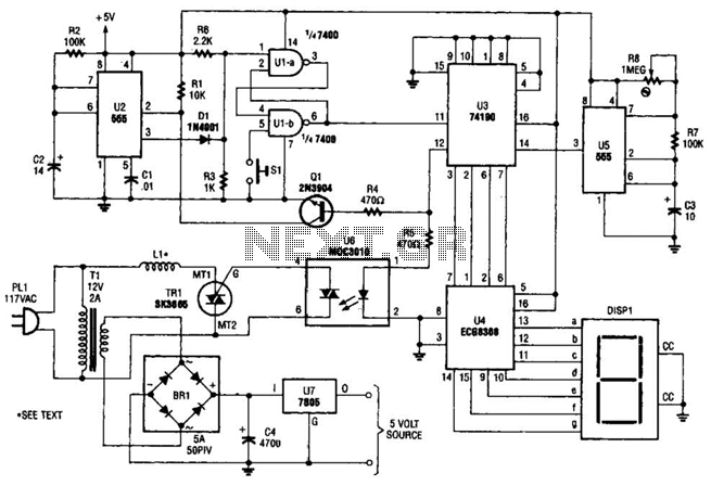
The electromagnetic ring launcher consists of four subcircuits: a clock circuit utilizing U5, a 555 oscillator/timer configured for astable operation; a countdown/display circuit incorporating U3, a 74190 synchronous up/down counter with BCD outputs set for countdown operation; U4, an...