
12 v battery charger max 20 a rms
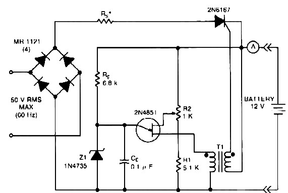
The 12V battery charger circuit is designed to provide efficient charging for lead-acid or lithium-ion batteries, ensuring that the battery is charged safely and effectively. The maximum output of 20 A RMS indicates that the charger can handle significant loads, making it suitable for various applications, including automotive and industrial uses.
The LM393 voltage comparator plays a crucial role in monitoring the charging process. It compares the voltage across the battery terminals to a reference voltage. When the battery voltage is below a certain threshold, the LM393 activates the charging process. As the battery charges and reaches the appropriate voltage level, the comparator deactivates the charger to prevent overcharging, which can damage the battery.
The D1 LED serves as a visual indicator of the charging status. When the charger is connected and current flows to the battery, the LED lights up, providing a clear indication that the battery is receiving charge. The requirement of at least 25 milliamps for the LED to illuminate ensures that the circuit only indicates charging when a significant current is present, thus reducing false positives.
Additional components in the circuit may include resistors for setting the reference voltage, capacitors for smoothing out voltage fluctuations, and diodes for preventing reverse current flow. Proper heat dissipation measures should also be implemented to ensure the longevity and reliability of the charger, especially under continuous high current conditions.
Overall, this 12V battery charger circuit with its integrated charging indicator not only enhances functionality but also improves user experience by providing real-time feedback on the charging status of the battery.12V battery charger Max : 20 A rms power supply. Go to that page to read the explanation about above power supply related circuit diagram. Description ofbatterycharger indicator: The circuit above willmakeyoursimplebatterychargerlook sophisticated. This circuit is a charging indicator forbatterycharger. It s usedtocheckwhether thebatteryis chargingornot. VoltagecomparatorLM393 ICis the heartofthis Battery charger indicator circuit. D1LEDstays litwhenthere areat least 25milli-amps of currentwhich flowsto the battery. This circuit isdesignedspecifically for12Vbatterywith. 🔗 External reference
Related Circuits
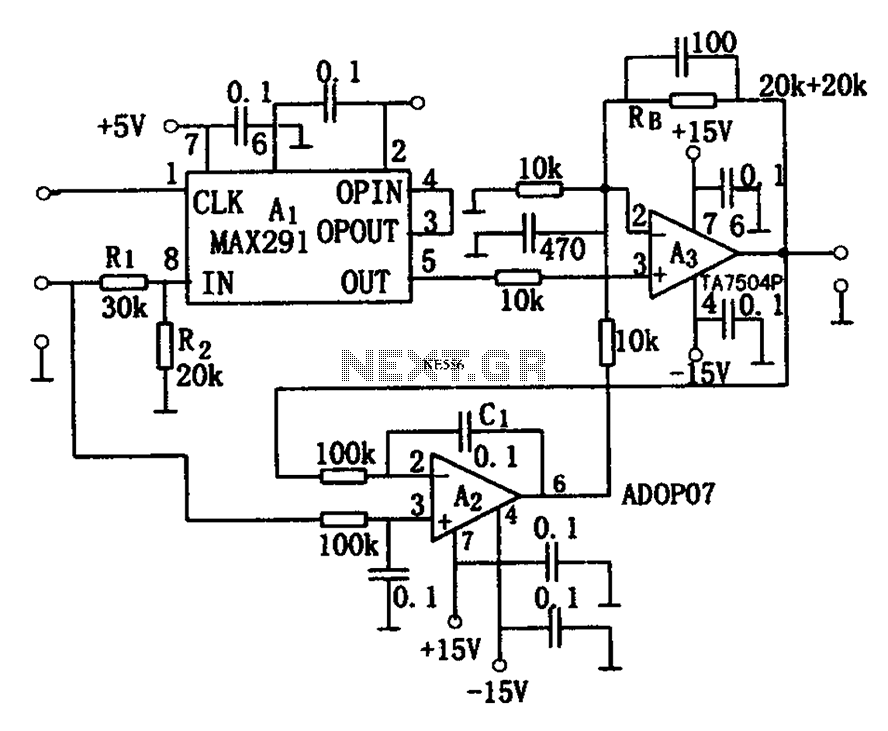
The circuit depicted in Figure 8 is a low-pass filter utilizing an eight-stage switched-capacitor configuration. The cutoff frequency of the circuit can be adjusted, with a clock frequency that can be modified to 1/100 of the original frequency. A...
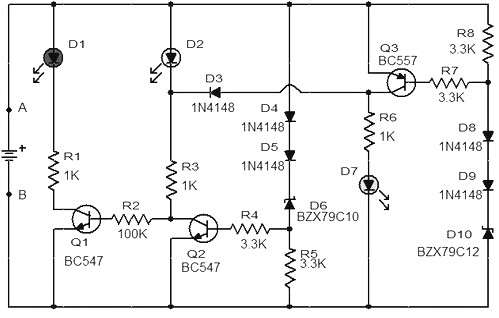
When the battery voltage is 11.5V or less, transistor Q1 is activated, and LED D1 will illuminate. When the battery voltage is between 11.5V and 13.5V, transistor Q2 is activated, causing LED D2 to light up. At a battery...
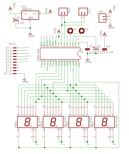
The MAX1496 is an analog-to-digital converter (ADC) that incorporates LED drivers, allowing for the construction of a 3 1/2 digit voltmeter using a minimal number of components. This device features both external and internal voltage reference options, along with...
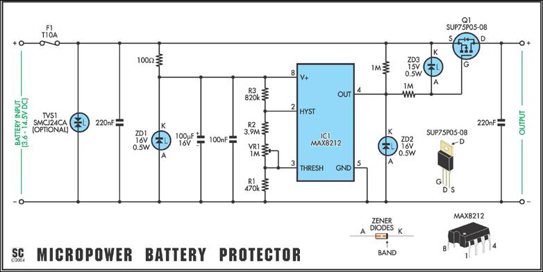
Protect expensive batteries from discharge damage with this mini-sized electronic cutout switch. It consumes minimal power and can be adapted to accommodate a wide range of battery voltages. In May 2002, Silicon Chip introduced the "Battery Guardian," a project...
Tests 1.5 to 15 Volt cells. This circuit runs a fast battery test without the need of power supply or expensive moving-coil voltmeters. It features two ranges: when SW1 is set as shown in the circuit diagram, the device...

This is a simple and low-cost NiCd and NiMH battery charger. The schematic diagram indicates that the charging current (I) should be set to 1/10 of the battery's rated capacity. For instance, if the battery has a rated capacity...