
Fast Battery Tester
The described circuit functions as a versatile battery tester capable of evaluating the performance of cells ranging from 1.5V to 15V. This is particularly beneficial for applications where a quick assessment of battery health is required without the need for external power sources or costly measuring instruments.
The circuit operates using a field-effect transistor (FET), designated as Q1, which is configured as a constant current generator. This configuration ensures that the current flowing through the LED (D1) remains stable regardless of variations in the battery voltage within the specified range. The illumination of LED D1 serves as an indicator of the battery's operational status, providing a visual cue that is easy to interpret.
The switch SW1 plays a critical role in determining the testing range. In one position, it allows the circuit to accommodate battery voltages from 3V to 15V, while the alternate position restricts the testing capability to 1.5V cells. This dual-range functionality is essential for a broad spectrum of battery types, including standard AA or AAA batteries as well as higher voltage cells used in various electronics.
Additionally, when the switch P1 is engaged, it connects the base of transistor Q2, which is responsible for applying a constant load to the battery. This load, approximately 120mA, is crucial for simulating real-world conditions under which the battery would typically operate. By applying this load, the circuit can accurately assess the battery's ability to deliver current, thus providing a reliable indication of its remaining capacity.
Overall, the design emphasizes simplicity and efficiency, with the dual LED display providing an intuitive interface for users to quickly ascertain battery status. The absence of a power supply requirement further enhances the circuit's portability and ease of use, making it an invaluable tool for technicians and hobbyists alike.Tests 1.5 to 15 Volt cells. This circuit runs a fast battery test without the need of power supply or expensive moving-coil voltmeters. It features two ranges: when SW1 is set as shown in the circuit diagram, the device can test 3V to 15V batteries.
When SW1 is switched to the other position, only 1.5V cells can be tested. Two-LED display, no power supply required. FET Q1 provides a constant current generator biasing LED D1 and Q2 Base. In this manner D1 illuminates at a constant intensity, independent of battery voltage from 3 to 15V and Q2 (when P1 is closed) applies a constant current load of about 120mA to the b 🔗 External reference
Related Circuits
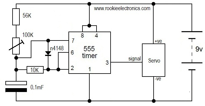
This is likely the simplest circuit to test a servo. It tests the speed of the servo using a potentiometer to control the speed. By applying a low voltage, such as 4.5V, and adjusting the potentiometer value, the position...

This compact circuit is designed to verify the basic functionality of an infrared remote control unit. It operates on the straightforward principle of connecting a piezo buzzer directly to an infrared (IR) receiver integrated circuit (IC). This approach is...
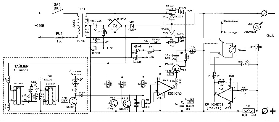
Charger for car battery power supply. Refer to the webpage for an explanation of the power supply-related circuit diagram. The battery charger indicator circuit described above enhances the appearance of a simple battery charger. This circuit serves as a...
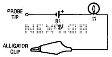
The continuity tester consists of a battery and a lamp connected in series, with one end of the circuit terminated with an alligator clip and the other end connected to the probe tip. The continuity tester is a fundamental...
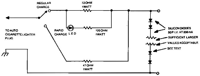
Car charger for NiCd battery packs power supply. This is a car NiCd battery charger circuit that can charge any Ni-Cd battery between 4.8 and 4.4 volts from a classic 12 volts car battery. The charging current is constant...
The continuity tester is a useful accessory to an ohmmeter. The unit or component whose continuity is to be checked is connected between terminals E1 and E2. A continuity tester is an essential tool in electronics for verifying the integrity...
Warning: include(partials/cookie-banner.php): Failed to open stream: Permission denied in /var/www/html/nextgr/view-circuit.php on line 713
Warning: include(): Failed opening 'partials/cookie-banner.php' for inclusion (include_path='.:/usr/share/php') in /var/www/html/nextgr/view-circuit.php on line 713