
Sealed Lead-Acid Charger
The circuit described utilizes the L200 voltage regulator, which is specifically designed for applications requiring adjustable output voltage and current limiting. The L200 can handle input voltages up to 40V and can output a maximum current of 3A, making it suitable for charging sealed lead-acid batteries.
The circuit should include a transformer to step down the AC mains voltage to a lower level suitable for the L200. A full-wave bridge rectifier is recommended to convert the AC voltage to DC, followed by a smoothing capacitor to reduce ripple voltage. The output from the rectifier should be connected to the input of the L200.
To set the desired output voltage for charging the lead-acid battery, a voltage divider can be used at the feedback pin of the L200. This allows for precise adjustment of the output voltage to match the battery's charging requirements, typically around 13.8V to 14.4V for sealed lead-acid batteries.
Current limiting can be implemented by placing a resistor in series with the load (the battery). The L200 has built-in current limiting features, allowing it to automatically reduce the output current if the battery approaches its maximum charging rate. This protects the battery from overcharging, which can lead to damage or reduced lifespan.
For float charging, the circuit should be designed to switch to a lower voltage once the battery reaches full charge. This can be achieved by using a relay or a transistor that senses the battery voltage and adjusts the output of the L200 accordingly. When the battery is fully charged, the output voltage can be reduced to around 13.2V, which is sufficient to maintain the charge without overcharging.
Finally, it is important to include appropriate heat sinking for the L200, as it may dissipate significant power during operation, especially when charging at higher currents. Adequate thermal management will ensure reliable operation and longevity of the components.
In summary, the charger design leveraging the L200 chip provides a robust solution for charging sealed lead-acid batteries efficiently and safely, while allowing for indefinite connection to the power source without the risk of damage to the battery.Here`s how to make a good charger for a sealed lead-acid battery (this will NOT work with NiCad batteries) that`s faster (because it allows more current into the battery initially) and safer (because it uses lower voltage when the charging is finished). The battery can be left plugged into this charger indefinitely, and it won`t bother it in the slightest.
In fact this is the "float" or "standby" charging method recommended by battery manufacturers. Below is a circuit based around an L200 chip. (Note to US residents: the L200 is more easily available in Eurpore than in the US. I hear that they are available in the US from BG Micro. If BG has run out, you may consider an equivalent made from an LM317 🔗 External reference
Related Circuits
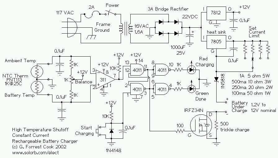
This circuit is designed for a temperature-controlled constant current battery charger, compatible with NiCd, NiMH, and other rechargeable cells. It operates on the principle that most rechargeable batteries exhibit an increase in temperature when they are fully charged. Overcharging...
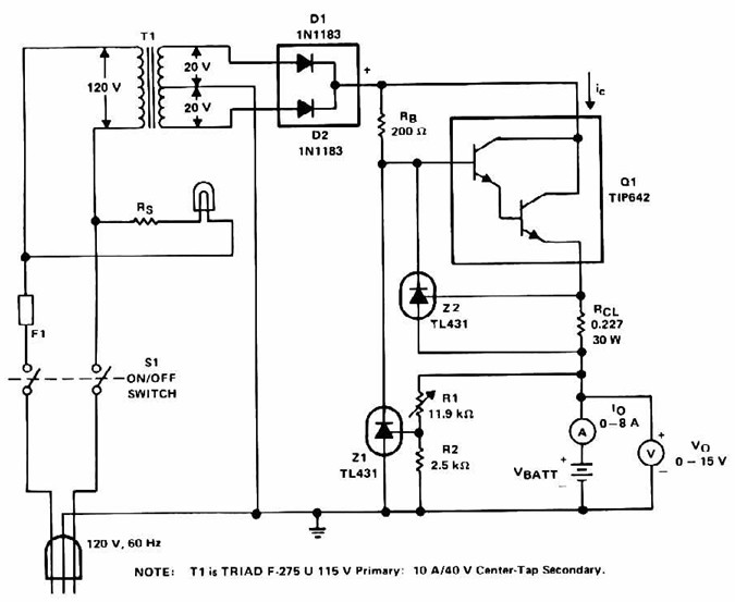
Lead Acid Battery Charger with current limit power supply. Refer to the specified page for an explanation of the related circuit diagram. The lead-acid battery charger with a current limit power supply is designed to safely charge lead-acid batteries while...
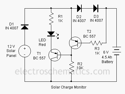
This add-on circuit can be attached to the solar charger to indicate whether the battery is charging. It lights a red LED to signal that the battery is charging. The described add-on circuit serves as a visual indicator for the...
This circuit serves as a standard battery charger and is specifically designed to maintain a 12-Volt Lead-Acid Battery, such as those used in flight boxes, in an optimal charged state. It is important to note that this circuit is...
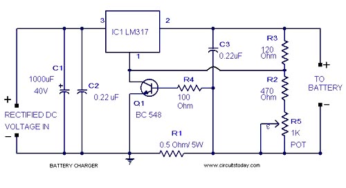
A simple lead-acid battery charger circuit with a diagram and schematic using the IC LM317, which provides the correct battery charging voltage. This lead-acid battery charger should be supplied with an input of 18 volts to the IC. The lead-acid...
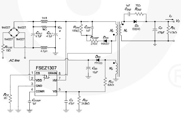
This cell phone charger circuit diagram electronic project is based on the FSEZ1307 third-generation primary side regulation (PSR) PWM controller integrated circuit. The FSEZ1307 cell phone charger can be used for battery charger applications for devices such as cellular...