
Power Path Management Battery Charger
Power management in electronic systems is critical, particularly in applications that necessitate simultaneous operation and battery charging. This dual functionality can lead to complex interactions between the system load and the charging circuit.
In a typical configuration, a power management integrated circuit (PMIC) is employed to oversee the power distribution between the system and the battery charger. The PMIC ensures that the system receives adequate power while the battery is being charged, preventing any interruptions in operation.
The schematic typically includes a battery management system (BMS) that monitors battery voltage, current, and temperature to optimize charging cycles and prolong battery life. The charger circuit can be a linear or switch-mode power supply, depending on the efficiency requirements of the application.
When the system is operational, the PMIC regulates the power drawn from the battery and the charger, allowing for seamless transitions between battery power and line power. This is often achieved through the use of power path management techniques, which ensure that the system can function without interruption even if the charger is disconnected.
Additionally, protection circuits are incorporated to safeguard against overvoltage, overcurrent, and thermal conditions, which could damage the battery or the system. These features are crucial in applications such as portable devices, where reliability and safety are paramount.
Overall, the design of a power management system that supports simultaneous operation and charging requires careful consideration of the interaction between the system load and the charging circuitry to ensure optimal performance and safety.Powering the system is required by many applications while charging the battery simultaneously. Interaction between the system and charger may result in a.. 🔗 External reference
Related Circuits
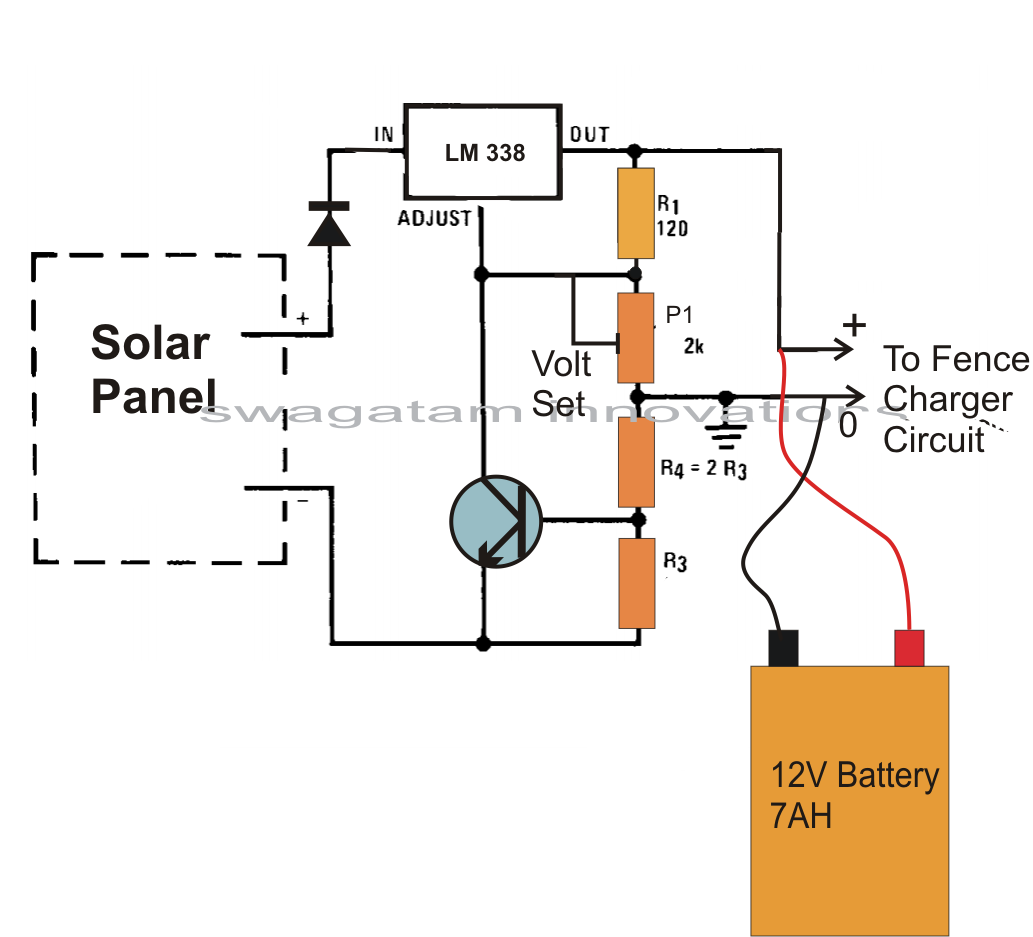
A fence charger, also known as an energizer, is a device used to electrify a fence or boundary to protect the enclosed area from human or animal intrusions. These boundaries are often located in large fields and parks, typically...
This document presents the circuit diagram of an IC-controlled emergency light with a charger, which functions as a 12V to 220V AC inverter circuit. The primary features of this circuit include automatic activation of the light during mains failure...
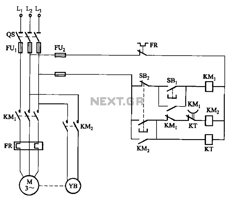
The circuit illustrated in Figure 3-123 operates as follows: When the stop button SBz is pressed, contact KMi releases, cutting off power to the motor. Simultaneously, KMz is activated, engaging the electromagnetic brake YB to hold the motor in...
A composite pipe can be reduced to facilitate the adjustment of the control current within the tube. Composite pipes are often utilized in various applications due to their lightweight, strength, and flexibility. When discussing the reduction of a composite pipe,...
The wide variety of automotive motor drivers, including those used for HVAC (heating, ventilation, and air conditioning), headlamp, seat positioning, window, and mirror applications, necessitates circuits that perform more than just switching the motor on and off. The drivers...
This circuit allows for the measurement of the actual output power of an amplifier. It can be housed in a box to function as a measurement instrument. The circuit for measuring amplifier output power typically includes a few essential components:...