
120V AC Lamp Dimmer
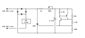
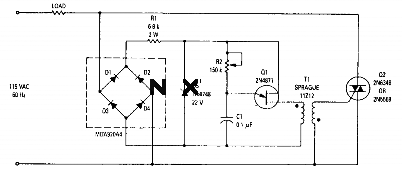
The full wave phase control circuit is designed to regulate the power delivered to a load by controlling the phase angle of the AC waveform. This circuit typically consists of four diodes arranged in a bridge configuration, allowing for the conversion of AC to DC while enabling control over the effective voltage applied to the load.
In this configuration, the load is connected in series with the AC line. When the AC voltage is applied, the diodes conduct current during both the positive and negative halves of the AC cycle, effectively allowing the load to receive power during both phases. The phase control is achieved by delaying the conduction angle of the diodes, which is done using a control circuit, often involving a triac or a similar device.
The control circuit determines the point in each half-cycle when the diodes will start conducting, thereby controlling the average power delivered to the load. This method is commonly utilized in applications such as light dimmers, motor speed controllers, and heating elements, where precise control over the power is necessary.
Key components of the circuit may include:
- Diodes: Four diodes configured in a bridge rectifier arrangement, which allows for full-wave rectification of the AC input.
- Control device: A triac or similar semiconductor device that can be triggered to control the phase angle.
- Load: The device or component that requires power, which is connected in series with the AC line.
The overall performance of the circuit can be influenced by several factors, including the characteristics of the load, the control method employed, and the design of the control circuit. Proper heat dissipation mechanisms may also be necessary to ensure reliable operation, particularly in high-power applications.The full wave phase control circuit below was found in a RCA power circuits book from 1969. The load is placed in series with the AC line and the four dio.. 🔗 External reference
Related Circuits
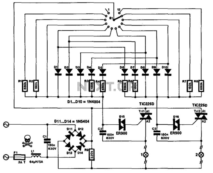
This specialized mains-operated dimmer for domestic or industrial lighting is not available in proprietary form. It enables brightness control of two groups of lights simultaneously. The possible combinations of brightness are outlined in a table. Continuous brightness control for...

It connects to the USB port and is ideal for checking motherboard switches and jumper settings. Many users may recall a commercial product from a few years ago, the "Itty Bitty Book Light," which was designed to clip onto...
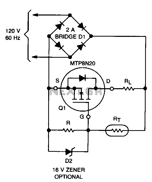
The lifespan of a lamp can be prolonged by enhancing the conditions under which its filament operates. This involves eliminating the inrush overcurrent surge and reducing the mechanical stress (vibration) on the filament caused by an AC source. The...
This schematic illustrates a simple yet effective LED dimmer circuit utilizing the well-known voltage regulator IC LM317T. The LM317T can function as a current regulator, as demonstrated in this circuit. It features ten super bright white LEDs, although the...
It is possible to reduce electricity bills by utilizing alternative power sources. The photovoltaic module, or solar panel, described here, can produce a power output of 5 watts. Under full sunlight conditions, the solar panel generates 16.5V and can...
This wide-range light dimmer circuit utilizes a unijunction transistor and a pulse transformer to implement phase control for the TRIAC. The circuit is designed to operate from a 115-volt, 60 Hz power source and can manage up to 800...
Warning: include(partials/cookie-banner.php): Failed to open stream: Permission denied in /var/www/html/nextgr/view-circuit.php on line 713
Warning: include(): Failed opening 'partials/cookie-banner.php' for inclusion (include_path='.:/usr/share/php') in /var/www/html/nextgr/view-circuit.php on line 713