
Four-Quadrant Dimmer
This mains-operated dimmer circuit is designed to enhance lighting control in both residential and industrial settings. The operation of the dimmer is based on the triac, a semiconductor device that can control power flow. The use of an RC network is critical, as it introduces a phase shift necessary for the triac to switch states effectively. The rotary switch allows users to select different resistors, which modulate the voltage applied to the lights, thus controlling their brightness. The four distinct brightness settings—full on, fully dimmed, one-third on, and two-thirds on—provide flexibility in lighting environments.
The design incorporates diodes that isolate the two lighting groups, preventing any interference that could arise from one group affecting the other. This is particularly important in applications where consistent lighting conditions are required. The choke and capacitor work together to filter out electrical noise, ensuring that the dimmer does not disrupt other devices connected to the same mains supply.
Thermal management is a key consideration in the design, with the triacs mounted on a heatsink rated for optimal heat dissipation. This allows the circuit to handle significant power loads—up to 500 W per group—without overheating. The enclosure must be designed with ventilation in mind, featuring adequate openings that allow airflow while safeguarding against accidental contact with live components.
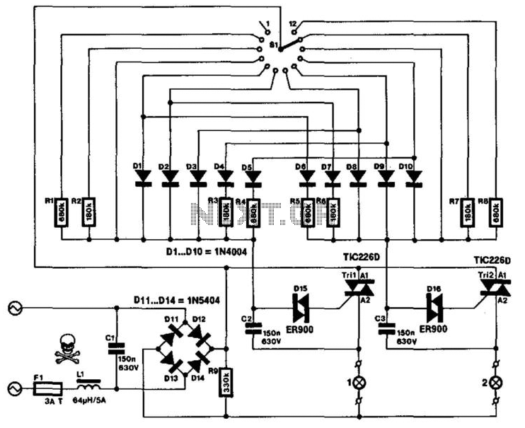
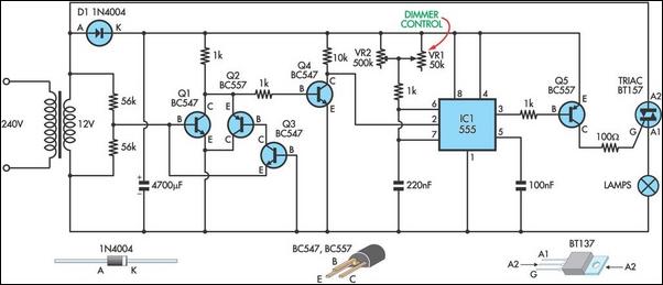
The choice of a non-metallic spindle for the switch enhances safety, reducing the risk of electric shock and allowing for a user-friendly experience. The inclusion of an ON indicator bulb is a practical feature that enhances user awareness of the system's operational status. Overall, this circuit exemplifies a thoughtful approach to lighting control, balancing functionality, safety, and user convenience in its design. This very special mains-operated dimmer for domestic or industrial lights is not available in proprietary form: it ena bles brightness control of two groups of lights in one operation. The possible combinations of brightness are shown in the table. It will be clear that it is not possible to obtain continuous brightness control in the two groups. Instead, the circuit affords the setting of four states of brightness in either group: full on, fully dimmed, V3 on, and 2/3 on. Both sections of the circuit operate on the well-known principle of the triac being switched from the blocking state to the conducting state with the aid of an RC network and a diode.
The RC network provides the necessary phase shift and determines when the triac is switched. The rotary switch selects the resistor in a given network, and thus the brightness of the relevant group of lights. No resistor means that the group is off; a short-circuit gives maximum brightness, and resistors of 10 KOhmhm and 18 kfi produce intermediate brightness.
The diodes prevent the groups from affecting one another. The 64- choke (Ll) and the 150 nF capacitor across the bridge rectifier prevent the dimmer causing interference in other equipment connected to the mains. If the triacs are fitted on a heatsink that is rated at 12° K/W, up to 500 W per group can be controlled.
It is, of course, essential that the enclosure in which the dimmer is fitted provides ample cooling. A fair number of slots or holes in it are, therefore, essential; these should not permit the circuit elements to be touched. The switch should have a nonmetallic spindle: this is not only safer than a metallic one, but it also enables the easy removal of the end-notch so that the switch can be rotated continuously, instead of having to be returned to the first stop every time it is operated.
The mains on/off switch S2 should be fitted with a built-in ON indicator bulb, which shows at a glance whether the circuit is on, even though SI might be in the OFF position. Finally, remember that this circuit carries mains voltage in many places: good workmanship and insulation are, therefore, of the utmost importance.
🔗 External reference
Related Circuits
This unique circuit makes your dome light look cool. Usually when the car door is closed, the dome light just goes OFF. With this circuit, you can have our dome light fade slowly in brightness and finally go OFF....
The electronic lantern control circuit adds high-efficiency dimming and flashing to an existing battery-powered lantern or flashlight or to a custom design. For the car it makes a great lamp for changing a flat tire, back seat reading or...
The circuit (before flameout) worked like this: device Q1 is a triac, which is a power-switching device. When triggered, it switches to a fully conducting state and stays that way until the current passing through it goes to zero....
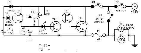
Every driver understands that intense light directed at the eyes can lead to hazardous consequences. Vehicles are equipped with a dimmer switch to reduce light intensity; however, some automotive headlamps remain excessively bright even when dimmed. The dimmer circuit...
A simple mains Light dimmer. A simple mains light dimmer is an electronic device used to adjust the brightness of incandescent and some LED lights by varying the voltage and current supplied to the light bulb. The typical operation of...
This circuit serves as the foundation for the dimmers in a model theatre lighting system that utilizes touch globes as the light source. The circuit is centered around a 55. This circuit design incorporates a dimmer functionality specifically tailored for...