
Light Chaser Circuit

The light chaser circuit is designed to create dynamic lighting effects that synchronize with music, enhancing the visual experience during performances or events. The configuration of five sets of 60W bulbs allows for bright and vibrant displays. Each set of bulbs can be individually controlled to turn on and off in a sequential manner, creating a chaser effect that moves along the zig-zag arrangement.
The core of the circuit typically includes a microcontroller or a dedicated music detection module that analyzes the audio input. This module processes the sound frequencies and triggers the bulbs based on the rhythm and beats of the music. The output control can be achieved through relays or triacs, which handle the high power requirements of the 60W bulbs while ensuring safe operation.
To enhance the functionality, additional features such as adjustable sensitivity to sound, variable speed control for the chaser effect, and the ability to select different lighting patterns can be incorporated. The power supply must be adequately rated to handle the total wattage of the bulbs, ensuring stable operation without overload. Proper heat dissipation methods should also be considered, especially if the circuit will be used for extended periods.
Overall, this light chaser circuit serves as an engaging tool for creating synchronized lighting displays that react to music, making it suitable for various applications, including parties, concerts, and theatrical performances.This light chaser circuit (music-operated lighting effect generator) comprises five sets of 60W bulbs that are arranged in zig-zag fashion. The bulb sets g.. 🔗 External reference
Related Circuits
This circuit was used to stop all the BFO drift. The circuit is extremely stable. Turn the receiver off, and then on at any time and temperature, the BFO frequency is exactly the same. The resonator is a Murata...

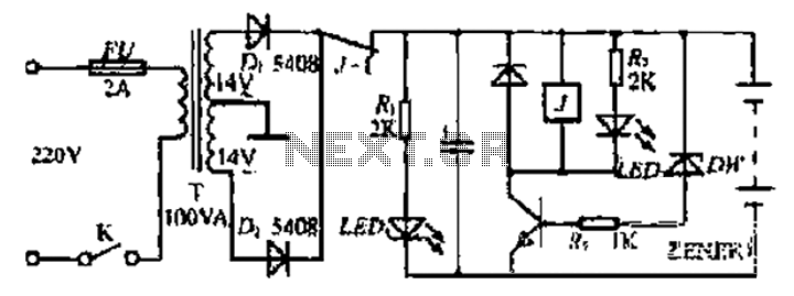
The car battery charging current is automatically limited to 4.2A. If there is a 600mV voltage on R1 (indicating 4A flowing through it), the T1 transistor begins to conduct. This prevents excessive charging current as the base current of...
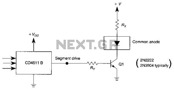
The use of a switching transistor, such as a 2N2222 or 2N3904, enables the operation of the CD4511B with a common-anode display. The transistor should be selected to provide approximately 1 mA to drive Q1, while resistor Rr must...
Bidirectional control is implemented for a motor to increase its operational degree. The motor can rotate in either direction with a current of 1A. A variable duty cycle multivibrator is utilized to achieve the construction and control of the...
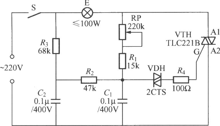
To address the lag and light transition issues, a Triac dimming light circuit featuring a dual time constant can be employed. This circuit enhances the resistor-capacitor network formed by R3 and C2. The reduced charge on capacitor C1 can...
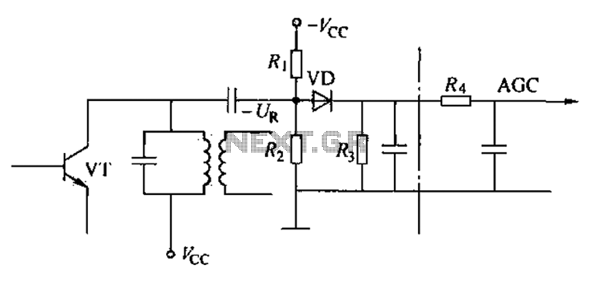
Commonly referred to as an automatic gain control (AGC) circuit, it is primarily utilized in receivers. This circuit maintains a constant output voltage amplitude despite variations in the input signal amplitude. It ensures that the receiver can effectively process...