
1296Mhz Rf Amplifier
The NEC70083 is a high-performance amplifier specifically designed for 1296 MHz applications, making it suitable for various RF communication systems. The amplifier's gain of 17 dB indicates its ability to significantly enhance the strength of incoming signals, which is essential for effective transmission and reception in radio frequency systems. The low noise figure of 1 to 1.5 dB ensures minimal degradation of signal quality, which is critical in maintaining clarity and integrity in communication.
The construction on a G-10 epoxy fiberglass PCB is chosen for its excellent dielectric properties and durability, which contribute to the overall reliability of the amplifier in various environmental conditions. The layout of the PCB must be followed precisely, as any deviation can lead to performance issues such as increased noise or reduced gain.
The power supply section is designed to deliver a steady 3 V DC, which is essential for the drain circuit to operate efficiently. The inclusion of a voltage regulator ensures that fluctuations in the supply voltage do not affect the amplifier's performance. Additionally, the negative bias generated by U2 is vital for controlling the gate voltage, which influences the amplifier's operational characteristics.
Resistor R5 plays a critical role in setting the drain voltage at +3 V, which is necessary for maintaining the desired operating point of the amplifier. Similarly, R3 is crucial for establishing the appropriate gate bias, which directly affects the amplifier's gain and linearity. The typical drain current of approximately 10 mA is indicative of the amplifier's power consumption and is a key parameter for designing power supply circuits.
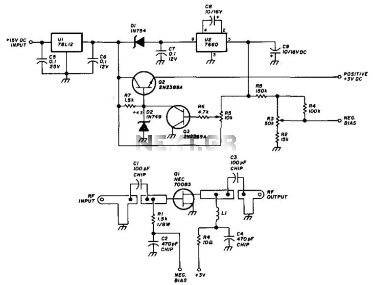
In conclusion, this 1296-MHz amplifier utilizing the NEC70083 is a well-engineered component that combines careful design considerations with high-performance specifications, making it an effective choice for RF applications. Using an NEC70083, this 1296-MHz amplifier delivers about 17-dB gain and around 1- to 1.5-dB noise. It is constructed on a G-10 epoxy fiberglass PC board. Use the layout shown because this is important for correct performance. The power supply/regulator delivers the regulated 3-Vdc for the drain circuit and U2 produces a negative bias for the gate circuit. R5 sets the drain voltage to+ 3 V and R3 sets the gate bias. Typically, the drain current is about 10 mA. 🔗 External reference
Related Circuits
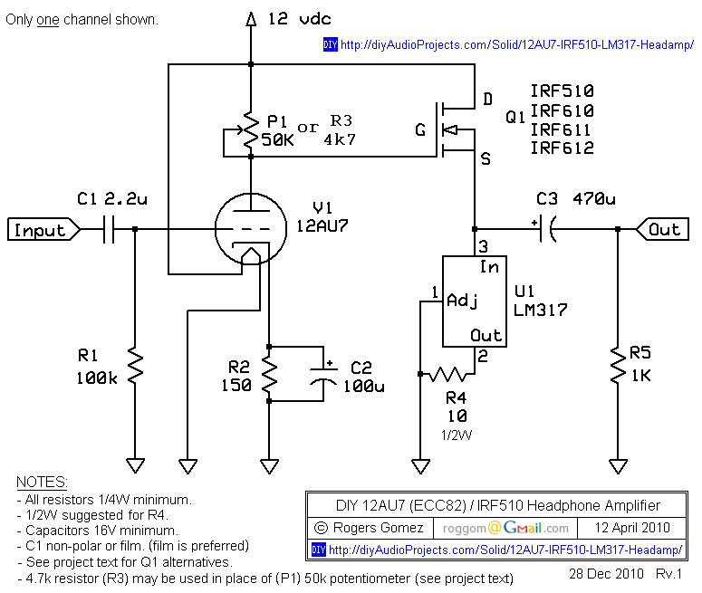
The NP-100v12 is a straightforward headphone amplifier designed for entry-level builders to assemble and listen to their own creation. The term "builder" refers to individuals with electronic experience and innovation, allowing them to create a device rather than merely...

A general-purpose preamplifier/mixer accepts up to four inputs, has a gain of 1600, and provides bass and treble controls that can be varied ± 10 dB at 100 Hz and 10 kHz respectively. More: IC1 and IC2 = LM301A. This...
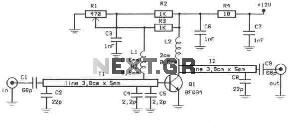
This amplifier is designed to amplify RF signals from an antenna by 10 dB and operates as a Class A amplifier using the BFQ34 transistor from Philips. The BFQ34 is packaged in an SOT122A case. The BFQ34T variant is...
The provided description pertains to a unique low voltage variant of an audio preamp. The emitter voltage of T1 is biased close to half the supply voltage, which is 1.5V. This biasing allows for the maximum output voltage swing. The...
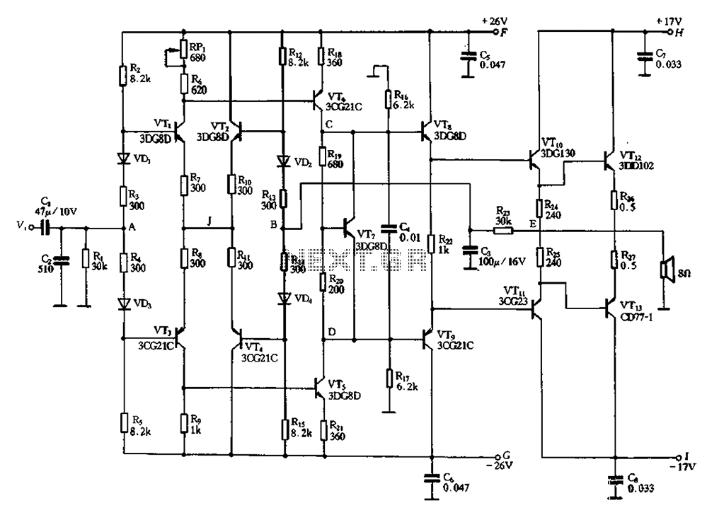
Almost all DC amplifier circuits are utilized as the input stage of differential circuits. Many complementary symmetry circuits also employ a double differential complementary sub-circuit along with a constant current source for the input stage. The constant current source...
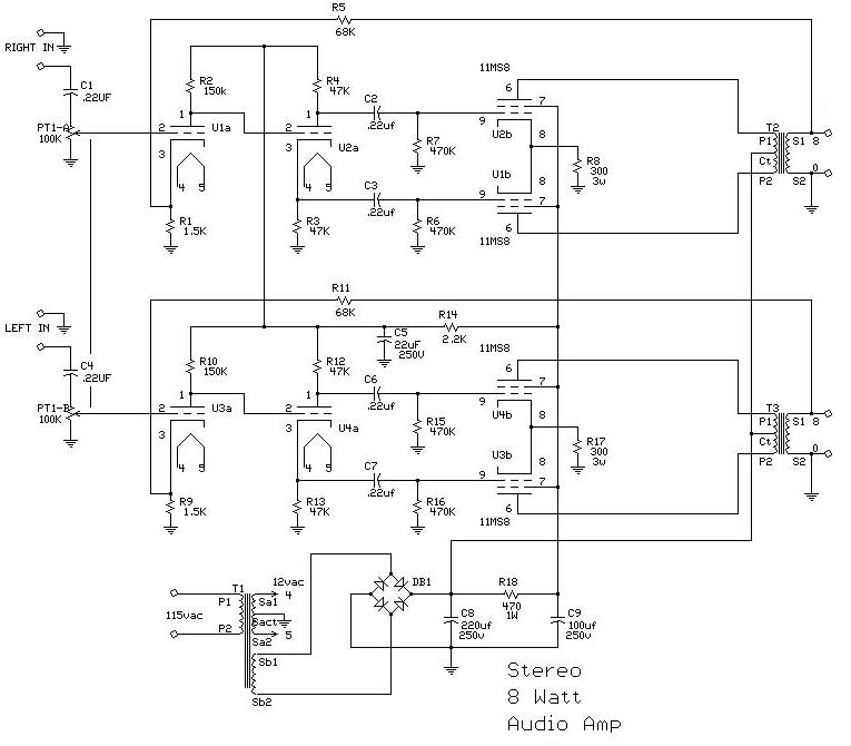
The 25-watt audio amplifier circuit is powered by a tube circuit. The tube transistor (TR) will amplify the input to approximately 20 watts, while a dual transformer can increase the output to 40 watts. A wide voltage range of...