
12V Car Battery Charger circuit

To initiate charging, TR1 should be adjusted to a null value, and the battery should be charged using the hydrometer technique. If the hydrometer is unavailable or unfamiliar, a battery in good condition can be used for charging. TR1 should be carefully adjusted until LD2 begins to illuminate and the charge current decreases to a few hundred milliamps (mA). If TR1 is correctly set, LD2 will flicker during subsequent charging cycles as the battery receives charge. Once the battery is fully charged, LD2 will illuminate steadily, and no further adjustments to TR1 will be necessary.
Transistor Q1 is in series with the battery and is activated by resistors R3, R4, and LD2. Components R2, C1, TR1, and diode D2 monitor the battery terminal voltage and trigger transistor Q2 when the voltage exceeds the threshold set by TR1. When an uncharged battery is connected, the terminal voltage remains low, keeping Q2 off while Q1 is activated during each half cycle by R3, R4, and LD2. Q1 acts as a rectifier, charging the battery. If the terminal voltage exceeds the predetermined level set by TR1, Q2 takes control of Q1, deactivating it and cutting off the current supply to the battery, while simultaneously illuminating LD2 to signal that charging is complete.
Both Q1 and bridge rectifier GR1 should be mounted on heatsinks to prevent overheating during operation. Additionally, M1 is a 5A DC ammeter used to measure the charging current. An optional voltmeter can be connected in parallel with the battery; however, it is essential that the voltmeter has a high input resistance to avoid affecting the measurement.The following circuit diagram is the battery charger for your 12V car battery. Unlike other battery chargers, this circuit featured overcharging protection which automatically disconnect the charging circuit. Most car battery chargers are simple devices that continuously charge the battery with a few amperes for the duration it is ON.
If the charg er is not switched OFF in time, the battery will overcharge, its electrolyte lost due to evaporation, and its plate-element will likely be destroyed. The circuit above will eliminate these problems by monitoring the battery`s condition of charge through its retroactive control circuit by applying a high charge current until the battery is completely charged.
When charging is complete, it turns on the red LED (LD2) and deactivates the charging circuit. This circuit is drawn to charge 12V batteries ONLY. Certain emphasis should be taken when wiring up this circuit. They are the connections of the transformer to the circuit board, and those supplying current to the battery being charged. These connections should be made with cables having a large cross-sectional area to prevent voltage-drop and heat build-up when current flows through them.
Adjust TR1 to null value and charge the battery using the hydrometer technique (if you do not have or do not know how to use a hydrometer, then use a good condition battery and charge). Carefully adjust TR1 so that LD2 begins to turn ON and the charge current falls to a few hundred milliamps (mA).
If TR1 is set correctly then in the next round of charging you will noticed LD2 begin to flicker as the battery is being charged. When battery is completely charged, LD2 turns ON completely. TR1 does not need further adjustment anymore. Q1 is connected in line with the battery and is fired by R3, R4 and LD2. The R2, C1, TR1 and D2 sense the voltage of the battery terminal and activate Q2 when the voltage of the battery terminal exceeds the value predetermined by TR1.
When an uncharged battery is connected, the terminal voltage is low. Under this circumstance, Q2 is turned OFF and Q1 is fired in each half cycle by R3, R4 and LD2. The Q1 functions as a simple rectifier and charges the battery. If the battery terminal voltage is increased above the level that had been fixed by TR1, then Q2 shifts the control of Q1 gate. This deactivates Q1 and cuts off the current supply to the battery and turns LD2 ON indicating that the charge has been completed.
Q1 and bridge rectifier GR1 should be mounted on heatsinks to prevent overheating. M1 is a 5A DC ammeter to measure the charge current. Optionally a voltmeter can be connected in parallel with the battery, however it must have a high input resistance so as not to influence the measurement. 🔗 External reference
Related Circuits
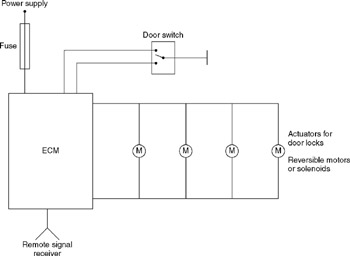
A central door locking system allows all doors, including the boot lid or tailgate, to be locked centrally from the driver's door, typically including the front passenger's door as well. The locking and unlocking actions are performed by an...
This simple circuit tests speakers, microphones, transformers, and voltage. It is essentially a very low-frequency oscillator that produces extremely short pulses. The sound produced is easy to hear and helps determine the precise direction it originates from, making it...
4V flat monitor high voltage power supply circuit diagram. A wide range of 7 to 40V to 5V DC-DC step-down circuit diagram. Light control switch circuit diagram for safety. Circuit 555 constitutes a control circuit diagram for photoelectric applications. The...
This solid-state push-pull single-ended Class A circuit is designed to deliver sound quality comparable to valve amplifiers, providing an output power of 6.9W measured across an 8 Ohm loudspeaker cabinet load. It features reduced total harmonic distortion (THD), increased...
This compact circuit enables automatic recording of phone conversations. It connects to the phone line, the microphone input of a tape recorder, and the remote control jack of the recorder. The circuit detects the voltage level in the phone...
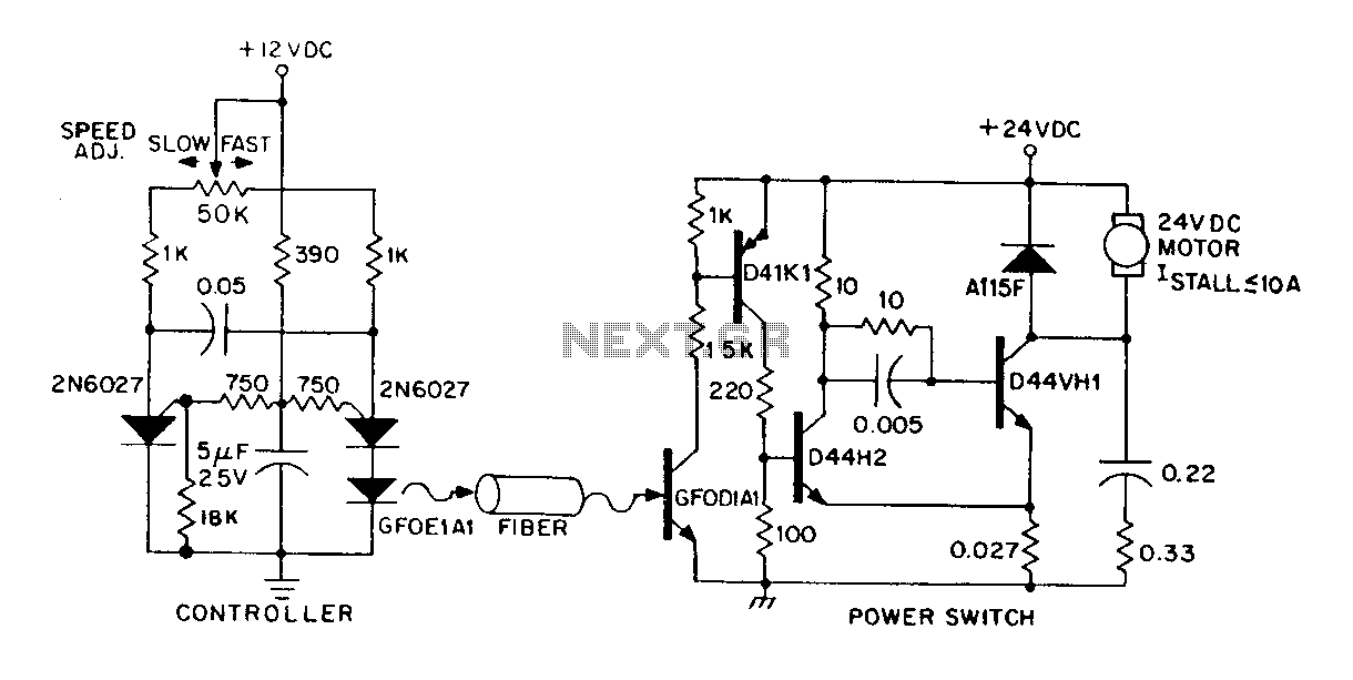
A DC power supply can be controlled through an optical fiber. The circuit includes a small DC motor (1/12 hp) that offers an isolated speed control channel. The control logic operates as an independent module, consuming 300 mW of...